SsangYong Stavic / SsangYong Rodius (2005 year). Manual - part 109
DI04-29
CHANGED BY
EFFECTIVE DATE
AFFECTED VIN
EXHAUST SYSTEM
DI ENG SM - 2004.9
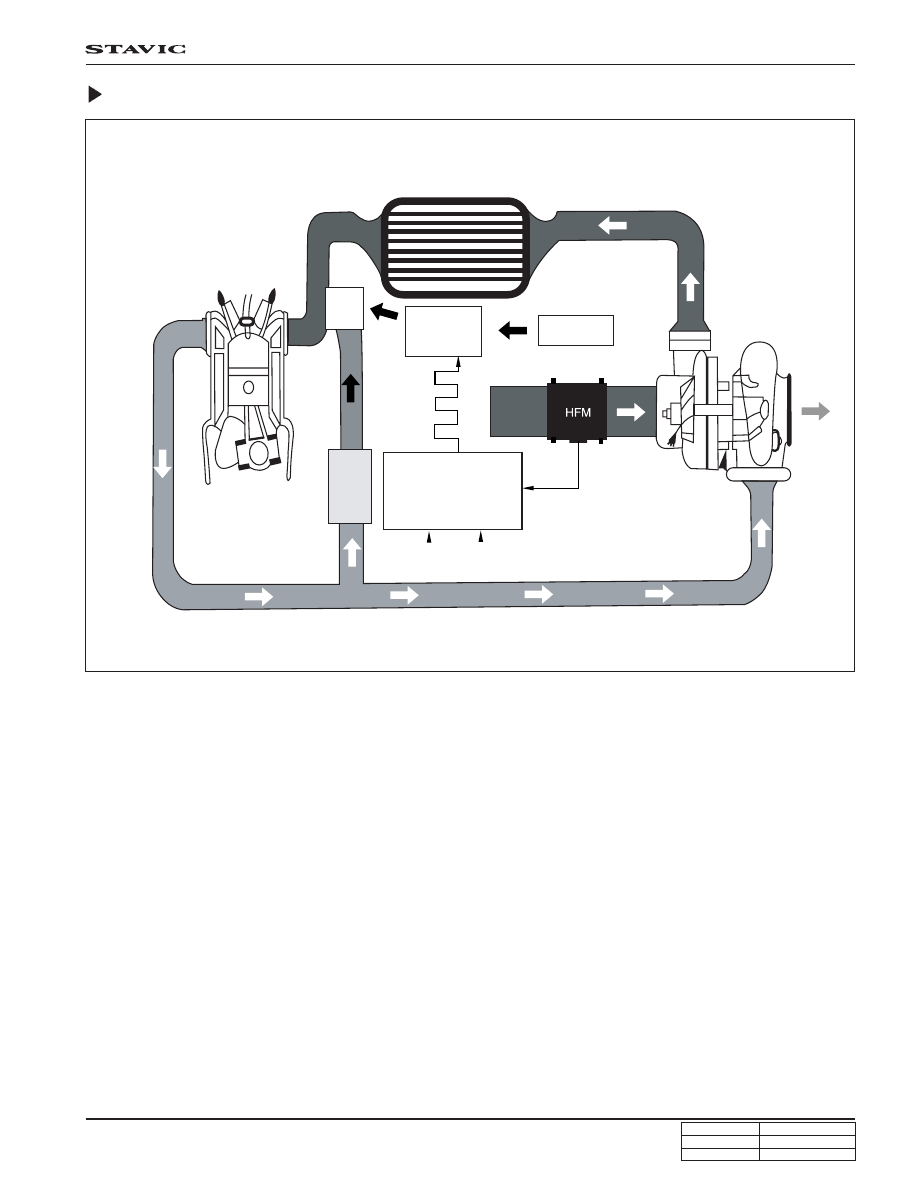
EGR System Diagram
EGR Valve
EGR valve recirculates some of exhaust gases to intake system to reduce toxic NOx from engine according to ECU
signals.
• EGR valve opening point : -270 mmHg
EGR Modulator
According to ECU signals, the vacuum modulator drives EGR valve by controlling vacuum pressure that is generated by
vacuum pump with PWM type controls.
Intercooler
Exhaust
manifold
Intake
manifold
EGR
valve
Regulated
vacuum
pressure
Modulator
Vacuum
pump
Duty
control
Feedback EGR
(Air Mass)
ECU
Improved target EGR
Air intake signal
(for EGR feed-
back control)
Turbo charger
Pedal
signal
RPM
signal