SsangYong Stavic / SsangYong Rodius (2005 year). Manual - part 98
DI03-5
CHANGED BY
EFFECTIVE DATE
AFFECTED VIN
INTAKE SYSTEM
DI ENG SM - 2004.9
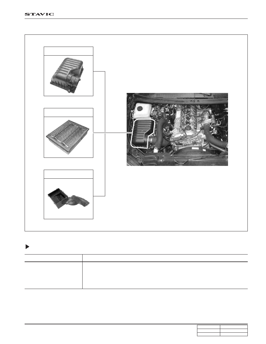
AIR CLEANER
Specifications
Cover
Element
Housing
Element Type
Dry-Element Type
* Initial cleaning: 5,000 km, Clean or change every 10,000 km as required.
However, change every 30,000 km.
* If the vehicle is operated under severe condition (short distance driving, extensive
idling or driving in dusty condition): More frequent maintenance is required.
Service Interval