SsangYong Stavic / SsangYong Rodius (2005 year). Manual - part 45
1F-21
CHANGED BY
EFFECTIVE DATE
AFFECTED VIN
ENGINE CONTROLS
M162 GSL ENG SM - 2005.7
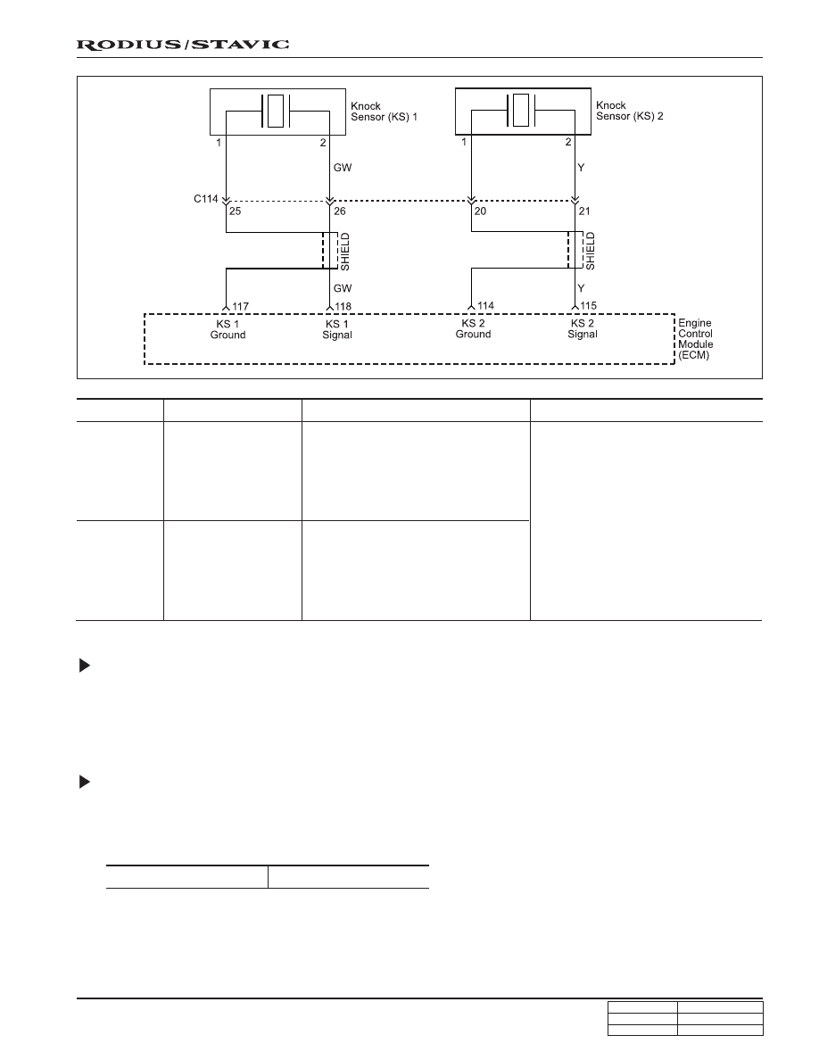
Circuit Description
The KS system is used to detect engine detonation, allowing the ECM to retard the ignition control spark timing based
on the KS signal being received. The KS signal’s amplitude and frequency depend upon the amount of knock being
experienced. The ECM monitors the KS signal and can diagnose the KS sensor and circuitry.
Knock Sensor Resistance Inspection
1. Disconnect the coupling from ECM while the ignition switch is in “OFF” position.
2. Measure the resistance between the coupling terminal pin No. 118 and No. 117 and terminal pin No. 115 and No.
114 using a multimeter.
Notice
Replace the KS if the measured values is out of the specified values. Check the connector and wire connection
between ECM and the KS if the measured values are normal.
Specified value
>10 M
Ω
Failur Code
Maintenance Hint
• Inspection the ECM pin 118,
117about short circuit or open with
bad contact
• Inspection the KS 1 malfunction
• Inspection the ECM
• Inspection the ECM pin 115, 114
about short circuit or open with
bad contact
• Inspection the KS 2 malfunction
• Inspection the ECM
Trouble Area
Description
57
When recognition in more than
control gain threshold at normal
operational condition of other
system during over 75 and 3,000 rpm
running area (cylinder 4, 5, 6)
No. 2 knock sensor
signal failure
56
When recognition in more than
control gain threshold at normal
operational condition of other
system during over 75 and 3,000 rpm
running area (cylinder 1, 2, 3)
No. 1 knock sensor
signal failure