SsangYong Stavic / SsangYong Rodius (2005 year). Manual - part 2
1A-3
CHANGED BY
EFFECTIVE DATE
AFFECTED VIN
GENERAL INFORMATION
M162 GSL ENG SM - 2005.7
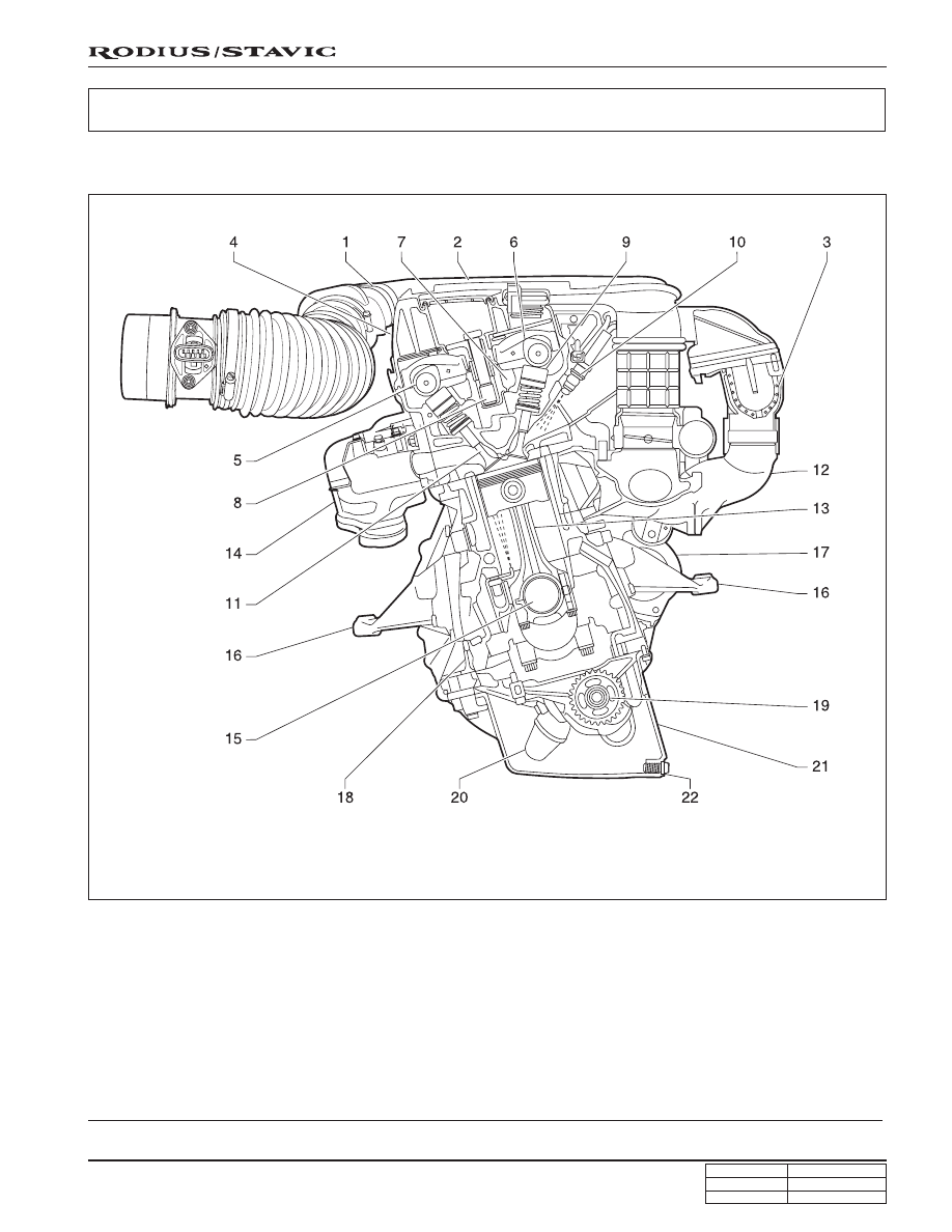
1. HFM sensor
2. Intake air duct
3. Resonance flap
4. Cylinder head cover
5. Exhaust camshaft
6. Intake camshaft
7. Cylinder head
8. Spark plug connector
COMPONENT LOCATOR
FRONT VIEW
9. Valve tappet
10. Injector
11. Exhaust valve
12. Intake manifold
13. Connecting rod
14. Exhaust manifold
15. Crankshaft
16. Engine mounting bracket
17. Starter
18. Crankcase
19. Oil pump sprocket
20. Oil strainer
21. Oil pan
22. Drain plug