SsangYong Korando III (2010 year). Manual - part 245


  Index      SsangYong     SsangYong Korando III - service repair manual 2010 year


Search            


Content   ..  243  244  245  246   ..


SsangYong Korando III (2010 year). Manual - part 245


11-26

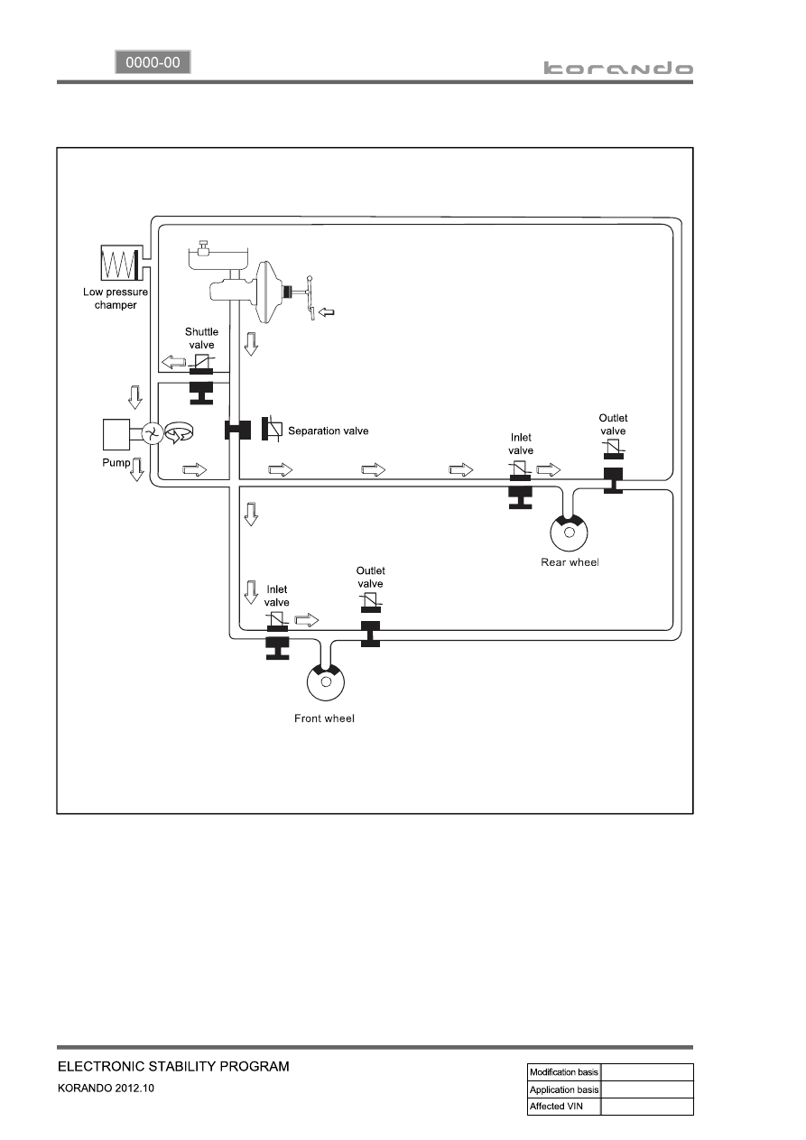
5) Hydraulic Circuit of HBA

The above figure shows one front and one rear wheel and the same hydraulic circuit forms as in the ESP 

operation. When HECU recognizes that it is an emergency and it is required for hard braking, depending 

on the pressure value of the brake pressure sensor and pressure changes caused by the pressure sensor 

timing, it operates the pump immediately to apply the brake pressure at the wheels. Then, the pressure in 

the pump increases until just before the corresponding wheel gets locked. The motor still keeps rotating 

and the outlet valve and the separation valve will stay closed. When the wheel starts to lock, the HBA 

function cancels and switches to ABS operation.

11-27

0000-00

7. CIRCUIT DIAGRAM

Wheel speed sensor, Stop lamp switch, Self diagnostic connector, Warning lamp (ABS/ESP)

▶ 

12-3

0000-00

1. SPECIFICATION (HPS)

Component

Item

Specification

Steering wheel

Type

3-spoke

Outside diameter

Φ 380 mm

Number of revolutions

3.11 rotations

Heated wire

Simple ON/OFF

Gear box

Type

Rack and pinion

Gear ratio

46.94

Rack stroke

± 73 mm

Steering angle

Inner

39°

Outer

31.24°

Wheel alignment

Toe-in

2 ± 2 mm

Oil pump

Type

Vane (removable pump and reservoir)

Maximum pressure

100 ± 3 bar

Displacement

6.0 to 9.75 ℓ/min

Pulley diameter

Φ 115 mm

Steering column

Tilting angle

Up

+ 2.0

Down

- 30

Lower shaft

Type

Ball slip

Steering oil

Oil type

ATF Dexron Ⅱ or Ⅲ

Oil reservoir capacity

1 ℓ

Change interval

EU (Diesel): Check and add at every 20,000 

km

GEN (Diesel, Gasoline): Check and add at 

every 15,000 km

Turning capability

Min. turning radius

5.4 m

12-4

2. TIGHTENING TORQUE

Item

Tightening torque

Remark

1. Power steering reservoir mounting bolt

8.8 to 13.7 Nm

12 mm x 2 EA

2. Power steering 
   pump

Upper mounting bolt/nut

25 ± 2.5 Nm

13 mm x 1 EA

Lower mounting bolt

25 ± 2.5 Nm

12 mm x 2 EA

3. Oil pipe 

Eye bolt (pump side)

53.9 to 63.7 Nm

22 mm

Steering gear box side nut

31.4 to 37.2 Nm

17 mm

4. Oil pipe bracket mounting nut

6.8 to 10.8 Nm

10 mm

5. Tie rod end lock nut

44.1 to 53.9 Nm

17 mm

6. Tie rod nut

63.7 to 78.4 Nm

22 mm

7. Lower shaft

Lower mounting bolt 
(gear box side)

17.6 to 24.5 Nm

12 mm

Upper mounting bolt (column 
side)

17.6 to 24.5 Nm

12 mm

8. Column shaft

Lower mounting bolt

19.6 to 24.5 Nm

12 mm

Upper mounting nut

19.6 to 24.5 Nm

12 mm

9. Steering wheel nut

39.2 to 58.8 Nm

22 mm

10. Loosened gear box mounting bolt/nut

Left: 98.0 to 127.4 Nm

17 mm

Right: 88.3 to 107.9 Nm

17 mm

11. Heat shield mounting bolt

8.8 to 13.7 Nm

12 mm x 2 EA


Content   ..  243  244  245  246   ..