SsangYong Korando III (2010 year). Manual - part 212
02-12
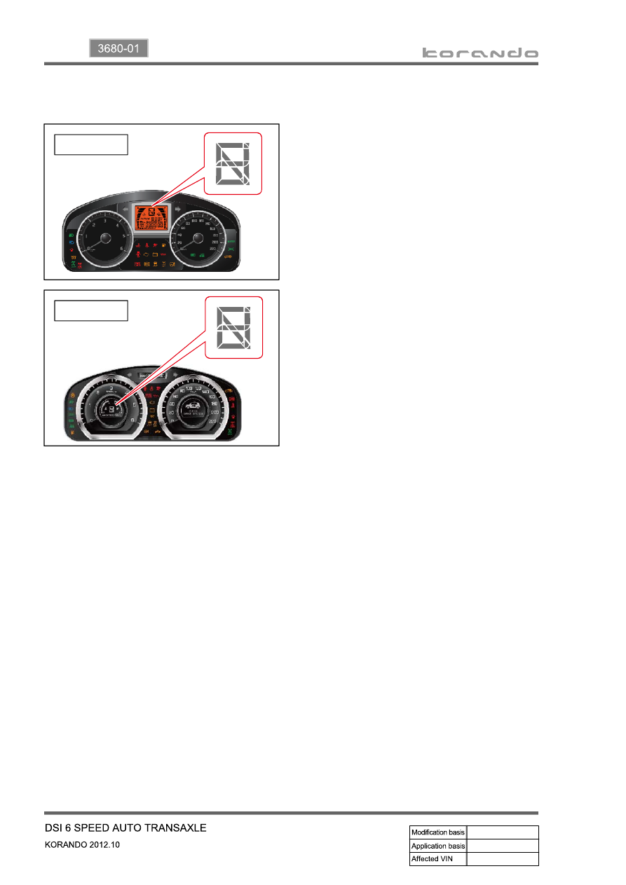
1st Gear State
▶
The 1st gear state will display on the
instrument cluster. Unlike the normal 1st gear,
engine braking will be available in this manual
1st state.
-
2nd Gear State
▶
The 2nd gear state will display on the
instrument cluster. 2-1 automatic kick-down
shifts are available. 2nd gear has engine
braking available.
-
3rd Gear State
▶
The 3rd gear state will display on the
instrument cluster. 3-2 and 3-1 automatic
kick-down shifts are available. 3rd gear has
engine braking available.
-
4th Gear State
▶
The 4th gear state will display on the
instrument cluster. 4-3 and 4-2 automatic
kick-down shifts are available. 4th gear has
engine braking available.
-
5th Gear State
▶
The 5th gear state will display on the
instrument cluster. 5-4 and 5-3 automatic
kick-down shift is available. 5th gear has
engine braking available.
-
6th Gear State
▶
The 6th gear state will display on the
instrument cluster. 6-5 and 6-4 automatic
kick-down shifts are available. 6th gear has
engine braking available.
-
STD type
SVC type