SsangYong Korando III (2010 year). Manual - part 72


  Index      SsangYong     SsangYong Korando III - service repair manual 2010 year


Search            


Content   ..  70  71  72  73   ..


SsangYong Korando III (2010 year). Manual - part 72


15-10

(2) Fuel Control

a. Fuel Pressure Control Elements

Pressure control consists of 2 principles.

Determines rail pressure according to engine operating conditions.

Controls IMV to make the rail pressure to reach to the required value.

-

-

Pressure in the fuel rail is determined according to engine speed and load on the engine.

When engine speed and load are high

The degree of turbulence is very great and the fuel can be injected at very high pressure in order to 

optimize combustion.

When engine speed and load are low

The degree of turbulence is low. If injection pressure is too high, the nozzle's penetration will be 

excessive and part of the fuel will be sprayed directly onto the sides of the cylinder, causing 

incomplete combustion. So there occurs smoke and damages engine durability.

-

-

Fuel pressure is corrected according to air temperature, coolant temperature and atmospheric pressure 

and to take account of the added ignition time caused by cold running or by high altitude driving. A 

special pressure demand is necessary in order to obtain the additional flow required during starts. This 

demand is determined according to injected fuel and coolant temperature.

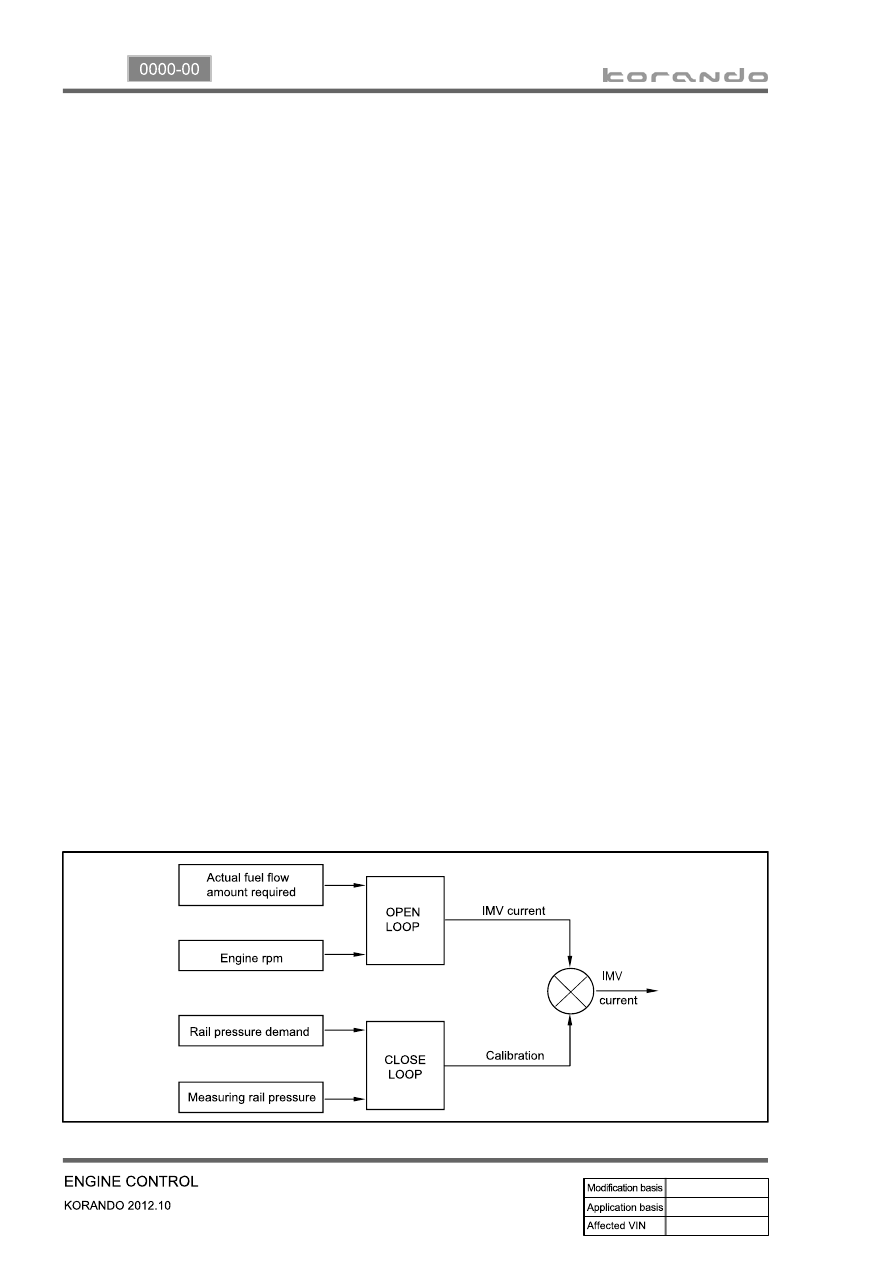
b. Fuel Pressure Control

Open loop determines the current which needs to be sent to the actuator in order to obtain the flow 

demanded by the ECU.

Closed loop will correct the current value depending on the difference between the pressure demand 

and the pressure measured.

If the pressure is lower than the demand, current is reduced so that the fuel sent to the high pressure 

pump is increased.

If the pressure is higher than the demand, current is increased so that the fuel sent to the high 

pressure pump is reduced.

-

-

Rail pressure is controlled by closed loop regulation of IMV.

15-11

0000-00

c. Fuel Injection Control

Injection control is used in order to determine the characteristics of the pulse which is sent to the 

injectors.

Injection control consists as below.

Injection timing

Injection volume

Translating fuel injection timing and injection volume into values which can be interpreted by the 

injector driver.

-

-

-

Main injection timing control

The pulse necessary for the main injection is determined as a function of the engine speed and of the 

injected flow.

The elements are:

A first correction is made according to the air and coolant temperatures.

This correction makes it possible to adapt the timing to the operating temperature of the engine. 

When the engine is warm, the timing can be retarded to reduce the combustion temperature and 

polluting emissions (NOx). When the engine is cold, the timing advance must be sufficient to allow 

the combustion to begin correctly.

A second correction is made according to the atmospheric pressure.

This correction is used to adapt the timing advance as a function of the atmospheric pressure and 

therefore the altitude.

A third correction is made according to the coolant temperature and the time which has passed since 

starting.

This correction allows the injection timing advance to be increased while the engine is warming up 

(initial 30 seconds). The purpose of this correction is to reduce the misfiring and instabilities which are 

liable to occur after a cold start.

A fourth correction is made according to the pressure error.

This correction is used to reduce the injection timing advance when the pressure in the rail is higher 

than the pressure demand.

A fifth correction is made according to the rate of EGR.

This correction is used to correct the injection timing advance as a function of the rate of exhaust gas 

recirculation.

When the EGR rate increases, the injection timing advance must in fact be increased in order to 

compensate for the fall in termperature in the cylinder.

-

-

-

-

-

During starting, the injection timing must be retarded in order to position the start of combustion close to 

the TDC. To do this, special mapping is used to determine the injection timing advance as a function of 

the engine speed and of the water temperature. 

15-12

Pilot injection timing control

The pilot injection timing is determined as a function of the engine speed and of the total flow.

The elements are:

A first correction is made according to the air and coolant temperatures. This correction allows the 

pilot injection timing to be adapted to the operating temperature of the engine.

A second correction is made according to the atmospheric pressure. This correction is used to adapt 

the pilot injection timing as a function of the atmospheric pressure and therefore the altitude.

-

-

d. Fuel Control

1. Main Flow Control

The main flow represents the amount of fuel injected into the cylinder during the main injection. The pilot 

flow represents the amount of fuel injected during the pilot injection. 

The total fuel injected during 1 cycle (main flow + pilot flow) is determined in the following manner.

When the driver depress the pedal, it is his demand which is taken into account by the system in order 

to determine the fuel injected.

When the driver release the pedal, the idle speed controller takes over to determine the minimum fuel 

which must be injected into the cylinder to prevent the enigne from stalling.


It is therefore the greater of these 2 values which is retained by the system. This value is then compared 

with the lower flow limit determined by the ESP system. 

As soon as the injected fuel becomes lower than the flow limit determined by the ESP system, the 

antagonistic torque (engine brake) transmitted to the drive wheels exceeds the adherence capacity of 

the vehicle and there is therefore a risk of the drive wheels locking.

The system thus chooses the greater of these 2 values (main flow & pilot flow) in order to prevent any 

loss of control of the vehicle during a sharp deceleration.

As soon as the injected fuel becomes higher than the fuel limit determined by the ASR trajectory control 

system, the engine torque transmitted to the wheels exceeds the adhesion capacity of the vehicle and 

there is a risk of the drive wheels skidding. The system therefore chooses the smaller of the two values 

in order to avoid any loss of control of the vehicle during accelerations.

The anti-oscillation strategy makes it possible to compensate for fluctuations in engine speed during 

transient conditions. This strategy leads to a fuel correction which is added to the total fuel of each 

cylinder. 

The main fuel is obtained by subtracting the pilot injection fuel from the total fuel.

A mapping determines the minimum fuel which can control an injector as a function of the rail pressure. 

As soon as the main fuel falls below this value, the fuel demand changes to 0 because in any case the 

injector is not capable of injecting the quantity demand.

A switch makes it possible to change over from the supercharge fuel to the total fuel according to the 

state of the engine.

Until the stating phase has finished, the system uses the supercharged fuel.

Once the engine changes to normal operation, the system uses the total fuel.

-

-

15-13

0000-00

2. Driver Demand

The driver demand is the translation of the pedal position into the fuel demand. It is calculated as a 

function of the pedal position and of the engine speed. The driver demand is filtered in order to limit the 

hesitations caused by rapid changes of the pedal position. A mapping determines the maximum fuel 

which can be injected as a function of the driver demand and the rail pressure. Since the flow is 

proportional to the injection time and to the square root of the injection pressure, it is necessary to limit 

the flow according to the pressure in order to avoid extending the injection for too long into the engine 

cycle. The system compares the driver demand with this limit and chooses the smaller of the 2 values. 

The driver demand is then corrected according to the coolant temperature. This correction is added to 

the driver demand.


Content   ..  70  71  72  73   ..