SsangYong Korando II (1996-2006 year). Manual - part 380


  Index      SsangYong     SsangYong Korando II - service repair manual 1996-2006 year


Search            


Content   ..  378  379  380  381   ..


SsangYong Korando II (1996-2006 year). Manual - part 380


HEATING AND VENTILATION SYSTEM  7A-17

SSANGYONG  MY2002

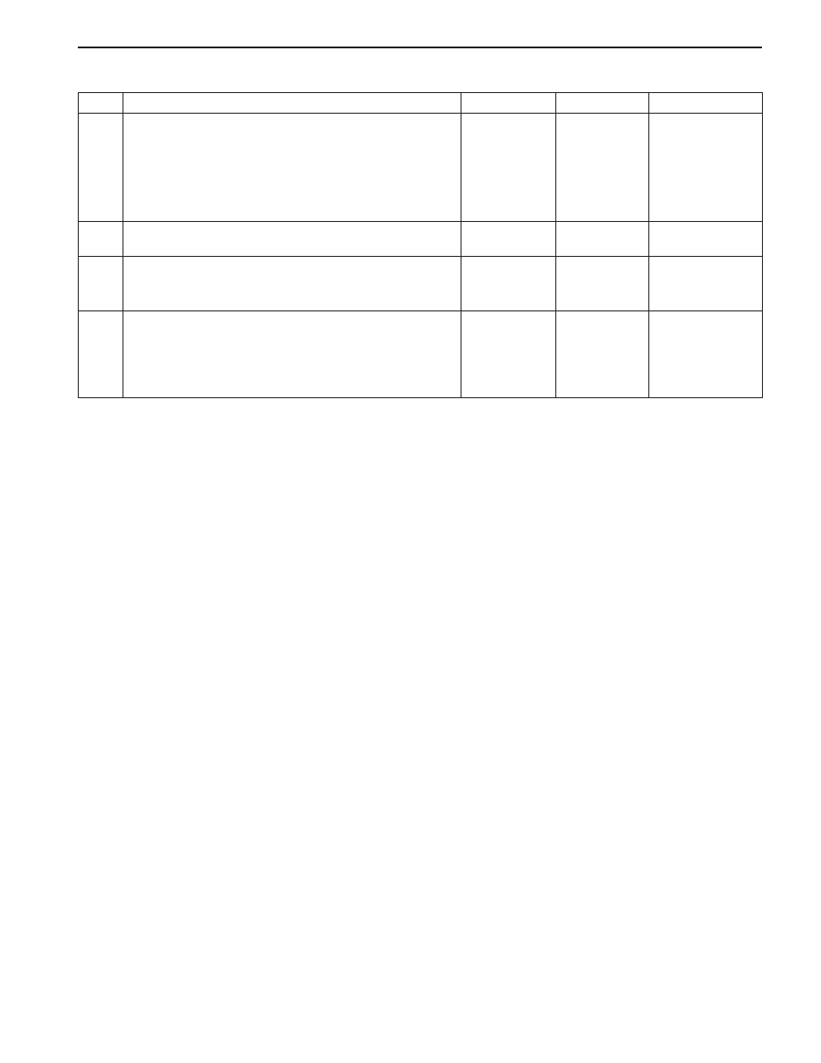
Blower Noise (Cont’d)

Step

15

16

17

18

Action

1. Check the ducts for obstruction or foreign materi-

als.

2. Remove any obstructions or foreign materials.
3. Check the vent door seals.
4. Repair or replace as needed.
Is the repair complete?
Is the noise present in all modes, but not all tempera-
ture positions?
1. Check the temperature door seals.
2. Repair or replace as needed.
Is the repair complete?
1. Check the system for obstructions for foreign

materials between the fan and the temperature
door.

2. Repair or replace as needed.
Is the repair complete?

Yes

System OK

Go to Step 16

System OK

System OK

No

-

Go to Step 18

-

Go to Step 2

Value(s)

SSANGYONG  MY2002

7A-18  HEATING AND VENTILATION SYSTEM

ON-VEHICLE SERVICE

TEMPREATURE CONTROL CABLE
ADJUSTMENT

Because the cable and the cable housing have fixed
lengths, it is impossible to make a temperature cable
adjustment.

The heater/air distributor case linkage also cannot be
adjusted.

If a malfunction is suspected, verify the proper
operation of the controller and the mechanical doors
for heater/air distributor case assembly.

MAINTENANCE AND REPAIR

KAA7A020

KAA7A030

CONTROLLER ASSEMBLY AND
TEMPERATURE CONTROL CABLE

Removal and installation Procedure

1. Disconnect the negative battery cable.

2. Slide the cable eyelet off the post on the

temperature door lever (under the I/P center).

3. Unsnap the clip that securing temperature control

cable.

Notice: Do not remove the bracket.

4. Remove the I/P center trim plate.

5. Remove four controller retaining screws.

6. Disconnect the electrical connectors.

7. Remove one screw that securing the temperature

control cable.

8. Disconnect the temperature control cable by gently

unsnapping the temperature control cable.

9. Remove and replace temperature control cable as

required.

10. Remove the controller assembly.

11. Installation should follow the removal procedure

in the reverse order.

HEATING AND VENTILATION SYSTEM  7A-19

SSANGYONG  MY2002

CONTROL ASSEMBLY KNOB
LIGHTING

Removal and installation Procedure

1. Disconnect the negative battery cable.

2. Remove the heating and ventilation control (HVC)

controller assembly. Refer to “Controller Assembly
and Temperature Control Cable” in this section.

3. Remove the connector cover by sliding away.

4. Remove the connector from the temperature control

cable control mechanism.

5. Separate the temperature control cable control

mechanism.

6. Turn the bulb holder to the left and pull out the

bulb.

7. Installation should follow the removal procedure

in the reverse order.

KAA7A040

KAA7A050

KAA7A060

AIR INTAKE DOOR ACTUATOR

Removal and Installation Procedure

1. Disconnect the negative battery cable.

2. Remove the glove box. Refer to Section 9E, Instru-

mentation/Driver Information.

3. Disconnect the connector to intake air control door

actuator.

4. Remove three screws that securing mode control

door actuator to heater/air distributor case.

5. Remove the mode control door actuator by gently

snapping the actuator.

6. Installation should follow the removal procedure

in the reverse order.

SSANGYONG  MY2002

7A-20  HEATING AND VENTILATION SYSTEM

MODE CONTROL DOOR
ACTUATOR

Removal and installation Procedure

1. Disconnect the negative battery cable.

2. Remove the driver knee bolster. Refer to Section

9E, Instrumentation/Driver Information.

3. Disconnect the connector to mode control door ac-

tuator.

4. Remove three sxrews that securing mode control

door actuator to heater/air distributor case.

5. Remove the mode control door actuator by gently

snapping the actuator.

6. Installation should follow the removal procedure

in the reverse order.

Tightening Torque

5 N•m (44 lb-in)

KAA7A070

KAA7A080

HEATER/AIR DISTRIBUTOR CASE
ASSEMBLY

Removal and installation Procedure

1 .Disconnect the negative battery cable.

2. Drain the cooling system. Refer to Section 1D, En-

gine Cooling.

3. Remove the inlet and outlet heater hoses from the

firewall.

4. Remove the instrument panel carrier assembly.

Refer to Section 9E, Instrumentation/Driver
Information.

5. Remove upper four bolts and lower two bolts on I/

P centers bracket.

Installation Notice

6. Remove the I/P center bracket.

7. Remove one screw and the joint duct for heater/

air distributor-to-rear heater duct.


Content   ..  378  379  380  381   ..