SsangYong Korando II (1996-2006 year). Manual - part 349


  Index      SsangYong     SsangYong Korando II - service repair manual 1996-2006 year


Search            


Content   ..  347  348  349  350   ..


SsangYong Korando II (1996-2006 year). Manual - part 349


SSANGYONG MY2002

5D1-72  TRANSFER CASE

KAA5D390

KAA5D400

KAA5D410

KAA5D420

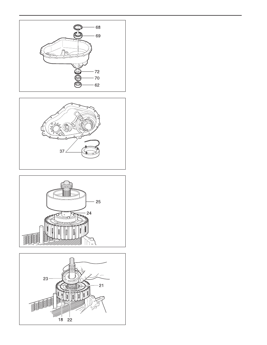
8. Remove the rear output shaft oil seal and discard

it, if required.

9. Remove the speedometer drive gear and rear pro-

peller shaft speed sensor tooth wheel.

10. Remove the internal snap ring that retains the rear

output shaft bearing in the bore.

Notice: Push the bearing from the outside of the
case.

14. Remove the balls, apply cam and wave washer

from the output shaft.

15. Remove snap ring from output shaft.

16. Remove clutch pack assembly from output shaft.

12. Remove thrust bearing from the rear output shaft.

13. Remove the clutch coil housing from the rear

output shaft.

11. Remove three nuts retaining the clutch coil assem-

bly and pull the clutch coil assembly along with
the wire from the case.

TRANSFER CASE  5D1-73

SSANGYONG MY2002

KAA5D430

KAA5D440

KAA5D450

KAA5D460

17. Remove the front propeller shaft speed sensor

tooth wheel.

18. Remove the chain, driven sprocket and drive

sprocket as an assembly.

19. Remove thrust washer from output shaft.

25. With expanding the tangs of the snap ring under

the planetary carrier assembly using SST snap ring
plier support the input shaft against a bench, push
the case down and slide the input shaft bearing.
Remove the input shaft and planetary carrier.

26. Remove and discard the input shaft oil seal as re

quired.

27. Remove the internal snap ring from the planetary

carrier and separate the planetary carrier from the
input shaft.

22. Remove the helical cam and shift rail as an assem-

bly by gently pulling out the shift rail. Check the
helical cam for damages and replace it if required.

23. Remove the high-low shift fork and high-low collar

as an assembly.

24. Remove the shift shaft.

20. Remove the magnet from the slot in the front of

the case bottom.

21. Remove the rear output shaft and oil pump as an

as-sembly.

Notice:  If there is removal resistance, do not
pound or use force to disassemble the pump. Do
not disassemble oil pump. It is serviced only as
an assembly. Check the pump to make sure the
pump rotates freely.

SSANGYONG MY2002

5D1-74  TRANSFER CASE

KAA5D470

KAA5D480

KAA5D490

KAA5D500

28. Remove the external snap ring from the input shaft.

29. Place the input shaft in a vise and remove the

bear ing.

30. Remove the thrust washer, thrust plate and the

sun gear off the input shaft.

Assembly Procedure

Important: Lubricate all parts with automatic transmis-
sion fluid (ATF) or equivalent before assemble. Remove

all traces of gasket sealant from the front case and
mounting adapter mating surfaces

1. Install the front output shaft bearing, if removed.

Notice: Press the bearing in straight, making sure
it is not cocked in the bore.

2. Install the internal snap ring that retains the front

output shaft bearing.

33. Remove the external snap ring retaining the front

output shaft.

34. Remove the front output shaft/flange.

35. Remove and discard front output shaft oil seal,

as required.

36. Remove the internal snap ring and remove the front

output shaft bearing, as required.

31. Position the input shaft on SST input shaft support.

32. Remove the needle bearing and bushing using

SST bearing installer/remover, as required.

Notice: Under normal use, the needle bearing and
bushing may not require replacement. After
inspection, If replacement is required, the bushing
and needle bearing must be replaced as a set.

TRANSFER CASE  5D1-75

SSANGYONG MY2002

KAA5D510

KAA5D520

KAA5D460

3. Install the front output shaft oil seal using oil seal

installer, if removed.

4. Install the front output shaft/flange and install the

snap ring.

8. Assemble the planetary carrier to the sun gear and

input shaft and install the internal snap ring to the
planetary carrier.

9. While expanding the tanged snap ring with SST

snap ring pliers install planetary carrier assembly.

10. Install the high-low shift fork and collar as an

assembly.

Notice: Make sure that the nylon wear pads are
installed on the shift fork and snapped securely
into place.

6. Slide the sun gear, thrust plate and thrust washer

into position on the input shaft.

Notice:  The recessed face of the sun gear and
the snap ring groove on the bearing outer race
should be toward the rear of the transfer case.
The stepped face of the thrust washer should face
toward the bearing.

7. Install the bearing over the input shaft using input

shaft bearing installer SST. Install the external snap
ring.

5. Install a new input shaft needle bearing and a new

bushing, if removed. Keep the following steps to
install the bearing and the bushing:

Position the input shaft on input shaft support.

Press a new needle bearing into the end of the
input shaft until it seats in the input shaft using
bearing remover/installer.

Press in a new bushing.


Content   ..  347  348  349  350   ..