SsangYong Korando II (1996-2006 year). Manual - part 315


  Index      SsangYong     SsangYong Korando II - service repair manual 1996-2006 year


Search            


Content   ..  313  314  315  316   ..


SsangYong Korando II (1996-2006 year). Manual - part 315


AUTOMATIC TRANSMISSION  5A-163

SSANGYONG  MY2002

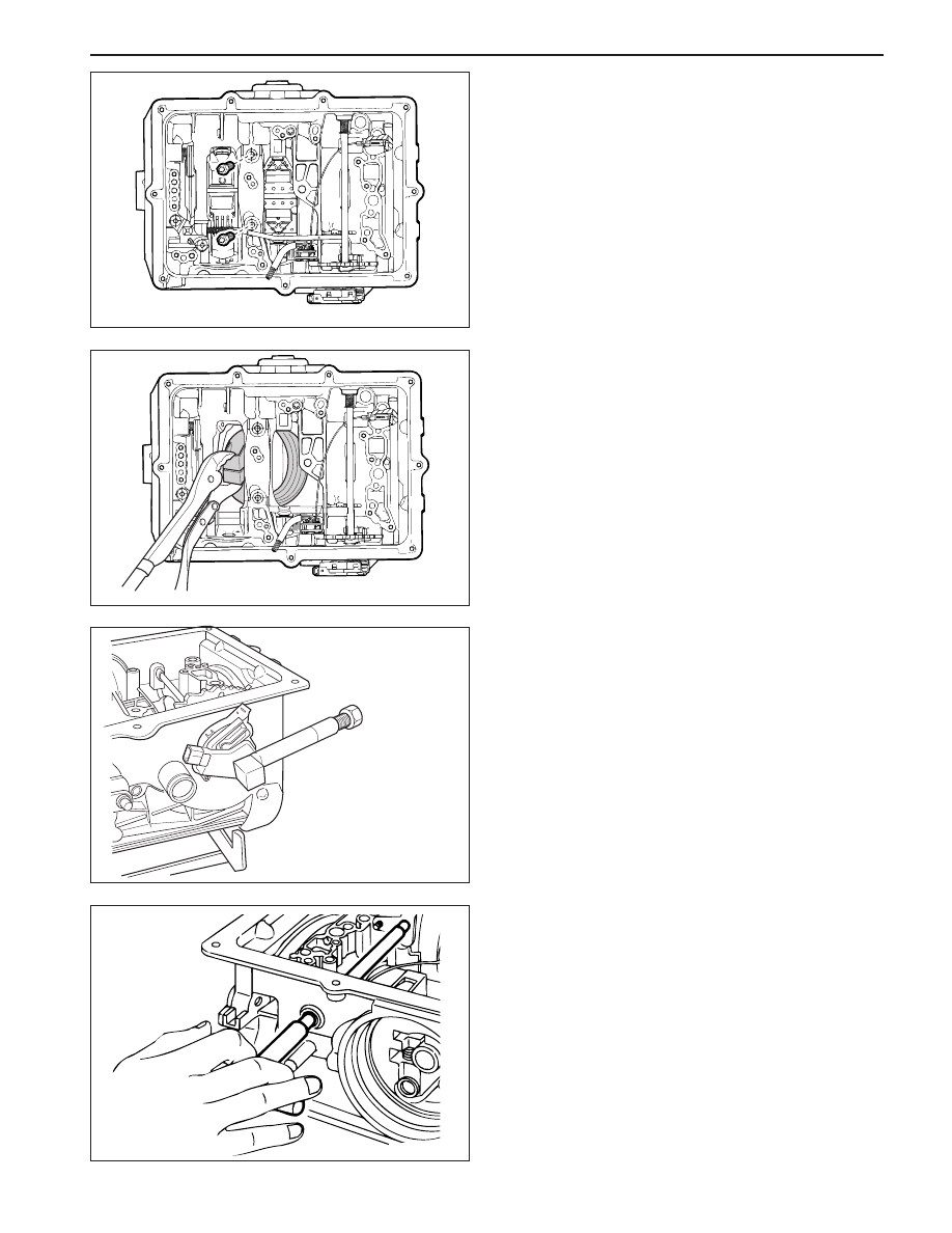
15. Remove the two centre support retaining bolts

using a T50 Torx bit.

16. Remove the centre support retaining circlip.

Notice: Do not hammer the output shaft to remove
the centre support as this will cause permanent
damage to the thrust bearing surfaces.

17. Remove the centre support, 1 - 2 one way clutch,

and planetary gear set as an assembly.

18. Remove the parking rod cam plate using a T40

Torx bit.

19. Remove the rear band struts and remove the band.

Notice: Vise the both end of rear band using the
plier and lean forward about 15 degrees

20. Remove the output shaft assembly.

Transmission Case

Tools Required

0555-336258 Cross Shaft Pin Remover/Installer

(Detent Lever)

0555-336261 Cross Shaft Seal Remover

0555-336265 Cross Shaft Pin Remover/Installer

(Inhibitor Switch)

1. Remove the pin from the side of cross shaft

inhibitor switch using cross shaft pin remover/
installer (inhibitor switch) 0555-336265.

2. Remove the inhibitor switch bolts and inhibitor

switch from the case.

3. Remove the cross shaft seals with cross shaft seal

remover 0555-336261.

4. Remove the circlip from the cross shaft. Pull the

shaft to release the drive pin from the selector
quadrant.

KAA5A560

KAA5A570

KAA5A580

KAA5A590

5A-164  AUTOMATIC TRANSMISSION

SSANGYONG  MY2002

5. Using cross shaft pin remover/installer (detent le-

ver) 0555-336258, press the pin from the cross
shaft and withdraw the shaft from the case.

6. Remove the cross shaft pin and spring.

7. Remove the manual valve lever and the park rod.

8. Depress the tangs and withdraw the 10 pin

connector into the case. Remove the wiring loom
assembly.

9. Detach the No. 7 solenoid wire from the front of

the case.

10. Remove the parking pawl pivot pin and the pawl

and spring from the case.

11. Remove the shaft and the rear servo lever.

12. Remove the rear servo cover and piston assembly.

13. Remove the B1R circlip, valve and spring.

14. Remove both band adjustment shims.

15. Inspect the output shaft bushing in the case and

replace if necessary.

16. Inspect cooler line fittings and replace as

necessary.

17. Inspect the case for damage.

KAA5A600

KAA5A610

KAA5A620

KAA5A630

AUTOMATIC TRANSMISSION  5A-165

SSANGYONG  MY2002

18. To remove the park rod lever: Remove the circlip

from the inner end of the pivot shaft and tap the
outer end of the shaft until it moves free from the
case, then using a wide shallow tapered drift as a
wedge, drive the pin out from the inside of the
case and remove the lever and spring.

Notice: Do not remove the park rod lever unless
absolutely necessary.

Forward Clutch Cylinder

Tools Required

0555-336259 Clutch Spring Compressor

1. Place the assembly in a horizontal position.

2. Remove the No. 4 needle bearing (2) and adjust-

ment shims (1) from the input shaft.

3. Remove the circlip from the front of the clutch cylin-

der and remove the input shaft.

4. Remove the overdrive shaft and the C1 clutch hub

assembly from the clutch cylinder.

5. Remove the C1 clutch plates from the cylinder.

6. Remove the circlip retaining the C3 clutch hub in

the rear of the clutch cylinder and remove the hub.

7. Remove the C2/C4 clutch hub assembly and

remove the No. 5 needle bearing from the C4 hub.

8. Removethe C2 clutch plates.

KAA5A640

KAA5A650

KAA5A660

KAA5A670

5A-166  AUTOMATIC TRANSMISSION

SSANGYONG  MY2002

9. Invert the clutch cylinder and remove the C4 clutch

sleeve, clutch plates and the two wave washers.
The 3 - 4 one way clutch is located between the
C2 and C4 clutch hubs, and the hubs may be
separated by rotating one hub clockwise and
withdrawing it from the other.

10. Remove the thrust block from the C4 clutch

cylinder hub.

11. Mount the clutch cylinder on clutch spring

compressor 0555-336259 with the C2/C4 end
uppermost and compress the piston return spring.
Remove the spring retaining circlip. Release the
tool and remove the circlip, keeper and spring.

Notice:  Make sure that the spring keeper is not
caught in the circlip groove, and that all the spring
pressure is released, before removing the tool.

12. Invert the clutch cylinder on the compressor tool

and removethe C1 clutch piston return spring in
asimilar manner.

13. To remove the clutch pistons from the clutch

cylinder, apply air pressure to the apply ports in
the bore of the cylinder.

C3 Clutch Cylinder

Tools Required

0555-336259 Clutch Spring Compressor

1. Remove the forward sun gear, No. 7 needle

bearing (2) thrust washer (1) and lipped thrust
washer (3) from the C3 clutch cylinder.

2. Remove the thrust plate (4), No. 6 needle bearing

(5), thrust plate (6) and nylon thrust plate (7) from
the clutch cylinder hub.

3. Remove the clutch plate retaining circlip and re-

move the clutch plates.

KAA5A680

KAA5A690

KAA5A700

KAA5A720


Content   ..  313  314  315  316   ..