SsangYong Actyon Sports II. Manual - part 75


  Index      SsangYong     SsangYong Actyon Sports II - service repair manual 2012-2013 year


Search            


Content   ..  73  74  75  76   ..


SsangYong Actyon Sports II. Manual - part 75


07-8

5) Jump Starting Procedure

Position the vehicle with the charged battery so that the jumper cables will reach from the charged 

battery to the battery that requires charging.

Turn off the ignition, all the lights, and all the electrical loads in both vehicles.

Leave the hazard flasher on if jump starting where there may be other traffic and any other lights 

needed for the work area.

Apply the parking brake firmly in both vehicles.

1.

2.

3.

4.

Shift an automatic transmission to PARK.

5.

Clamp one end of the first jumper cable to the positive terminal on the booster battery. Make sure it 

does not touch any other metal parts.

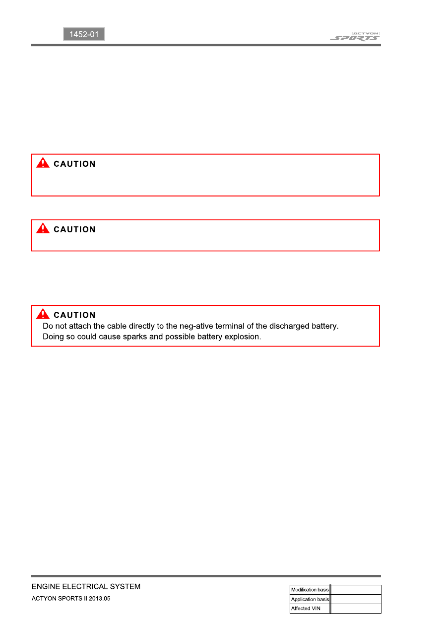
Clamp the other end of the same cable to the positive terminal on the discharged battery. Never 

connect the other end to the negative terminal of the discharged battery.

6.

7.

Clamp one end of the second cable to the negative terminal of the booster battery.

Make the final connection to a solid engine ground, such as the engine lift bracket at least 450 

millimeters (18 inches) from the discharged battery.

Start the engine of the vehicle with the good battery. 

Run the engine at a moderate speed for several minutes.

Then start the engine of the vehicle with the discharged battery.

Remove the jumper cables by reversing the above sequence exactly, removing the negative cable 

from the vehicle with the discharged battery first. 

While removing each clamp, take care that it does not touch any other metal while the other end 

remains attached.

8.

9.

10.

11.

12.

In order to avoid damaging the vehicle make sure the cables are not on or near pulleys, fans, or 

other parts that will move when the engine starts.

In order to avoid injury, do not use cables that have loose or missing insulation.

07-9

1452-01

6) Alternator

Alternators are equipped with internal regulators. 

Unlike three-wire generators, the alternator may be used with only two connections: battery positive and 

an "D+" terminal to the charge indicator lamp.

As with other charging systems, the charge indicator lamp lights when the ignition switch is turned to 

RUN, and goes out when the engine is running. 

If the charge idicator is on with the engine running, a charging system defect is indicated. This indicator 

light will glow at full brilliance for several kinds of defects as well as when the system voltage is too high 

or too low.

The regulator voltage setting varies with temperature and limits the system voltage by controlling rotor 

field current.

Achieve correct average field current for proper system voltage control by varying the on-off time. At high 

speeds, the on-time may be 10 percent and the off-time 90 percent. 

At low speeds, with high electrical loads, the on-time may be 90 percent and the off-time 10 percent.

7) Charging System

Generators use a new type of regulator that incorporates a diode trio. 

A Delta stator, a rectifier bridge, and a rotor with slip rings and brushes are electrically similar

to earlier generators. 

A conventional pulley and fan are used. 

There is no test hole.

8) Starter

Wound field starter motors have pole pieces, arranged around the armature, which are energized by 

wound field coils.

Enclosed shift lever cranking motors have the shift lever mechanism and the solenoid plunger enclosed 

in the drive housing, protecting them from exposure to dirt, icy conditions, and splashes. 

In the basic circuit, solenoid windings are energized when the switch is closed. 

The resulting plunger and shift lever movement causes the pinion to engage the engine flywheel ring 

gear. 

The solenoid main contacts close. Cranking then takes place.

When the engine starts, pinion overrun protects the armature from excessive speed until the switch is 

opened, at which time the return spring causes the pinion to disengage.

To prevent excessive overrun, the switch should be released immediately after the engine starts.

07-10

9) Starting System

The engine electrical system includes the battery, the ignition, the starter, the generator, and all the 

related wiring.

Diagnostic tables will aid in troubleshooting system faults. When a fault is traced to a particular 

component, refer to that component section of the service manual. 

The starting system circuit consists of the battery, the starter motor, the ignition switch, and all the related 

electrical wiring. 

All of these components are connected electrically.

08-3

1521-01

1. ENGINE DATA DISPLAY TABLE


Content   ..  73  74  75  76   ..