SsangYong Actyon Sports II. Manual - part 61


  Index      SsangYong     SsangYong Actyon Sports II - service repair manual 2012-2013 year


Search            


Content   ..  59  60  61  62   ..


SsangYong Actyon Sports II. Manual - part 61


15-41

0000-00

D. Cooling fan and A/C compressor control

Conditions for cooling fan

The cooling fan module controls the cooling fan relay, high speed relay and low speed relay. The cooling 

fan is controlled by the series and parallel circuits.

A/C switch

Cooling fan

Coolant temperature

Refrigerant pressure

A/C 

compressor

OFF 

OFF 

Coolant temp. < 90℃ 

LO 

90℃ ≤ Coolant temp. 

 < 105℃

HI 

105℃ ≤ Coolant temp. 

ON

LO 

Coolant temp.  < 105℃

Refrigerant pressure < 

18 bar

ON

HI 

18 bar ≤ Refrigerant 

pressure 

HI 

105℃ ≤ Coolant temp.  

< 115℃

HI

115℃ ≤ Coolant temp. 

OFF (cut)

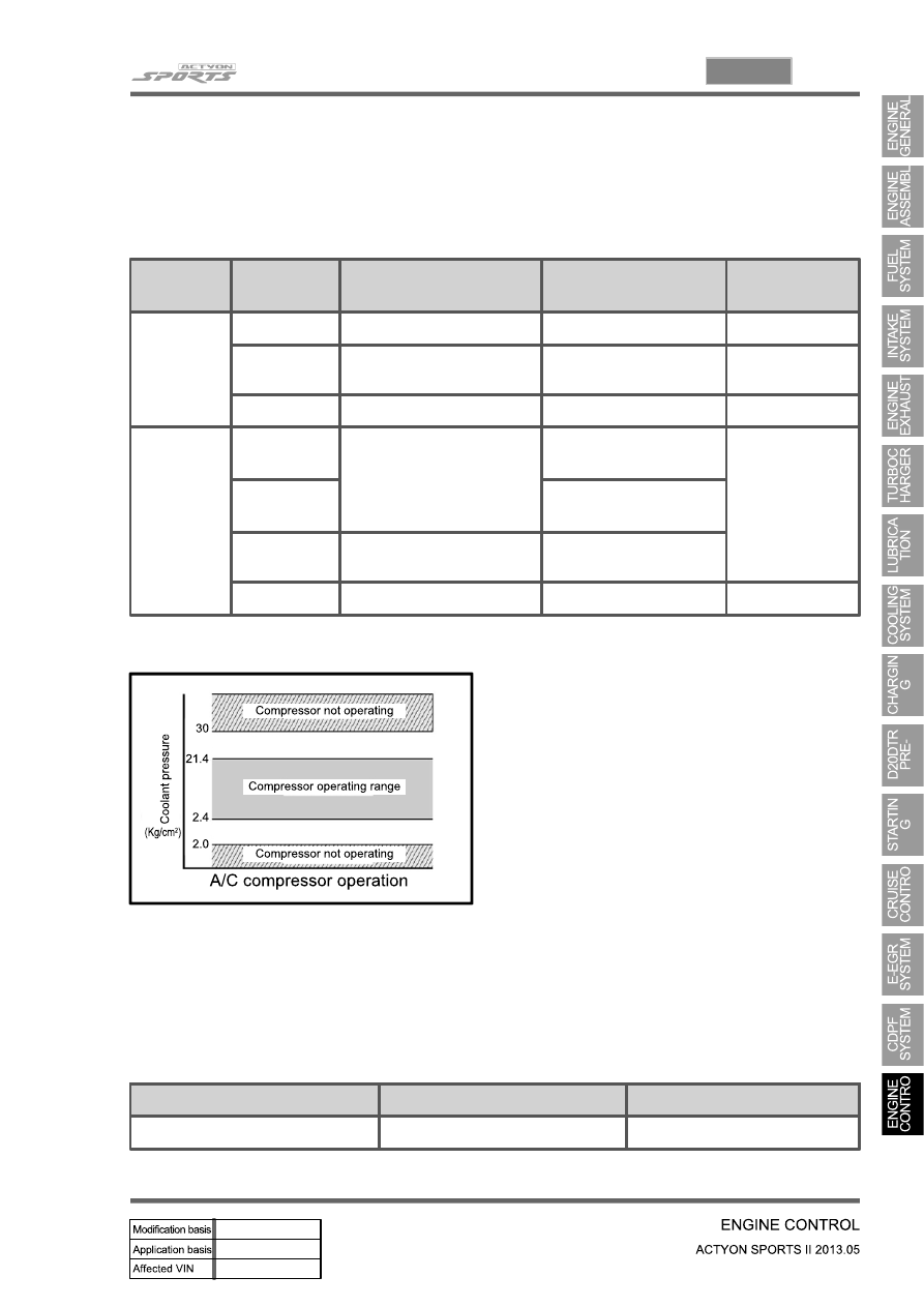
A/C compressor OFF conditions

Coolant temperature: below -20℃ or over 
115℃

Approx. 4 seconds after starting the engine

Engine rpm: below 650 rpm or over 4500 rpm 

When abrupt acceleration

Refrigerant pressure:
* OFF below 2.0 kg/㎠, then ON over 2.4 kg/㎠ 
* OFF over 30 kg/㎠, then ON below 21.4 kg/㎠

-

-

-

-

-

The output voltage from refrigerant pressure sensor is 1.7 V to 3.5 V when the refrigerant pressure is 10 
to 24 kgf/㎠ with A/C "ON".

Output voltage according to refrigerant pressure

Cooling fan controls according to ATF

ATF temperature

Fan condition

Remark

Over 110˚C

High speed

15-42

Relay box in engine compartment

(13) PTC heater control

A. Overview

The supplementary electrical heater is installed in DI engine equipped vehicle as a basic equipment. The 

PTC system is operated according to two temperature values measured at the coolant temperature 

sensor and HFM sensor. This device is mounted in the heater air outlet and increase the temperature of 

air to the passenger compartment. Because PTC system is heated by electrical power, high capacity 

alternator is required. PTC does not operate during engine cranking, while the battery voltage is lower 

than 11 V or during preheating process of glow plugs.

B. Components

HFM (intake air 

temperature)

Coolant temperature 

sensor

PTC heater

PTC 2 relay (PTC 

heater 2, 3)

PTC heater 

3 (40A)

PTC heater 

2 (40A)

PTC heater 

1 (40A)

D20DTR ECU

PTC 1 relay 

(PTC heater 1)

15-43

0000-00

C. Operation process

The ceramic PTC has a feature that the resistance goes up very high at a certain temperature. There 

are three circuits in PTC heater. Only one circuit is connected when PTC1 relay is ON, and two circuits 

are connected when PTC2 relay is ON.
Operation process: reaches at a certain temperature→high resistance→low current→less heat 
radiation→temperature down→high resistance→high current→temperature up

15-44

D. Control conditions

Operation

Operating condition

PTC Heater

HI

(PTC2)

- Coolant temperature < 15℃

PTC  HI ON

LO

(PTC1)

- Coolant temperature 15℃ ≤ 65℃, intake air 
   temperature ≤ -10℃
- Coolant temperature 15℃ < 65 to 60℃, intake air 
   temperature <-10℃ to 0℃
- Coolant temperature 15℃ ≤ 60℃, intake air 
   temperature ≤ 0℃ to 5℃

PTC  LO ON

Stop

- A/C blower switch OFF
- Defective ambient air temperature sensor
  (including open or short circuit)
- Engine cranking
- Low battery voltage (below 11V)
- During pre-glow process (glow indicator ON)

Operation diagram for PTC heater LO (step 2)


Content   ..  59  60  61  62   ..