Skoda Kodiaq (2019 year). Manual - part 7


  Index      Skoda     Skoda Kodiaq (2019 year) - manual in english


Search            copyright infringement  


Content      ..     5      6      7      8     ..


Skoda Kodiaq (2019 year). Manual - part 7


CAUTION

Never exceed the maximum permissible load of the respective fasteners,

nets, hooks etc. - these could be damaged.

Make sure that the heating elements of the rear window heater, the ele-

ments of the integrated aerial in the rear window or in the rear side windows

are not damaged by abrasive items.

Do not place sharp objects in the nets and storage compartments in the lug-

gage compartment - there is a risk of damage to the net as well as the com-

partments.

Put the items in the storage compartments carefully and not load these

punctiform - there is a risk of damage to the compartments.
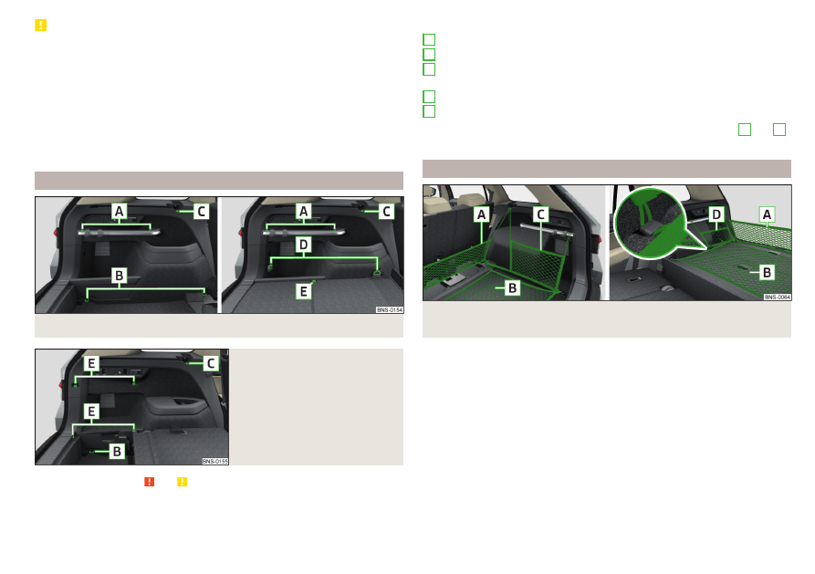
Fastening elements

Fig. 142  Fastening elements: Version 1/version 2

Fig. 143 

Fastening elements: Variant 3

Read and observe   and   on page 108 first.

The fasteners are located on both sides of the luggage compartment.

Overview of the fastening elements 

» Fig. 142

and 

» Fig. 143

Mounting bar with integrated hooks for fixing fastening nets.
Lashing eyes for fastening cargo and securing nets
Fixing hooks of fastening systems in the trough of the foldable luggage

compartment cover
Lashing eyes for fastening cargo and securing nets
Hooks for securing fastening nets

The maximum permissible static load for the individual lashing eyes 

B

 and 

D

is 350 kg.

Fixing nets

Fig. 144  Fastening examples for nets: Fastening examples for nets: five-

seat version/five-seat version with the variable loading floor

A
B
C

D

E

109

Transport of cargo

-------------------------------------------------------------------------------------------------------------------------------------------------------------

Fig. 145  Fastening examples for nets: Seven-seat version

Read and observe   and   on page 108 first.

Fastening examples for nets 

» Fig. 144

 and 

» Fig. 145

Horizontal pocket
Floor net
Vertical pocket
Longitudinal net
Variable net

The maximum permissible load of each of the nets is 1.5 kg.
If also equipped with the variable loading floor and the spare or emergency

wheel five-seat version, the lashing eyes 

D

 can be used for securing the longi-

tudinal pocket 

» Fig. 142

 on page 109.

Fastening strip with moveable hook

Fig. 146  Sliding hook onto the fastening strip/removing hook

A
B
C
D

E

Read and observe   and   on page 108 first.

A fastening bar is located on both sides of the luggage compartment with two

moveable hooks each, in order to attach small items of luggage, such as bags,

etc.
The maximum permissible load of each of the hooks is 7.5 kg.

Moving the hook

Hold hook upward in direction of arrow 

1

 and move to the desired position

in the direction of arrow 

2


» Fig. 146

.

Fold down the hook until it stops in the arrow direction 

3

.

Removing hooks

The hook can be removed only in the front area of the attachment bar.

Fold the hook upwards in direction of arrow 

4


» Fig. 146

 until it disengages,

and remove in the direction of arrow 

5

.

Inserting hook

The hook can be removed only in the front region of the attachment bar.

Position the hook on the fastening strip in a vertical position in direction of

arrow 

5

 and lightly press on it 

» Fig. 146

.

Fold down the hook until it stops against the direction of arrow 

4

.

Foldable hook

Fig. 147 

Fold down hook

Read and observe   and   on page 108 first.

One foldable hook for attaching small items of luggage, such as bags etc., is

provided on each side of the luggage compartment.

To use it, pull down the hook in the direction of the arrow 

» Fig. 147

.

110

Operation

-------------------------------------------------------------------------------------------------------------------------------------------------------------

The maximum permissible load of the hook is 7.5 kg.

Fasten the flooring

Fig. 148 

fixing the floor covering

Read and observe   and   on page 108 first.

The floor covering can be fixed by means of a hook on the frame of the lug-

gage compartment lid 

» Fig. 148

.

CAUTION

Do not lift the floor covering too high when attaching the hook - there is a risk

of damage to the roof trim.

Floor covering on both sides

Read and observe   and   on page 108 first.

A double-sided floor covering can be fitted in the luggage compartment. One

side is made of fabric, the other side is washable (suitable for transporting wet

or dirty items ).

CAUTION

The double-sided flooring can be used in the five-seat variant, and for vehicles

without the variable loading floor.

Roll-up cover

Fig. 149  Roll-up cover: extending/retracting/removing

Fig. 150  Stowing the roll-out cover

Read and observe   and   on page 108 first.

Extending

Grasp the cover at grip-point 

A

 and pull it out in the direction of the arrow

1

 until it audibly clicks into place

» Fig. 149

.

111

Transport of cargo

-------------------------------------------------------------------------------------------------------------------------------------------------------------

Retracting

Push the cover in the handle area 

A

 in the direction of arrow 

2


» Fig. 149

.

The cover rolls up automatically. The rolled-up cover can now be removed.

Removing/inserting

Press on the side of the cross bar in the direction of arrow 

3

 and remove

the cover in the arrow direction 

4


» Fig. 149

.

To insert, proceed in reverse order.

Stowing - seven-seat variant

The removed roll-up cover can be stowed in the recesses of the luggage com-

partment side trim.

Lift the variable loading floor in direction of arrow 

1

 and slide cover into the

side recesses 

» Fig. 150

.

Open the side pockets on both sides of the luggage compartment in the di-

rection of arrows 

2

.

Insert the roll-up cover in an inclined position in the recess of the right side

panel in the direction of arrow 

3

 and stow in arrow direction 

4

.

Close the side pockets on both sides of the luggage compartment in the op-

posite direction to arrow 

2

 and restore the original position of the variable

loading floor.

WARNING

No objects should be placed on the roll-up cover - there is a risk of damage

to the cover and a risk of injury in the event of a sudden stop or a vehicle

collision!

CAUTION

It is possible that the roll-up luggage compartment cover rolls more slowly

during winter weather conditions. This is not a defect.

Net partition

Fig. 151  Net partition behind the rear seats

Read and observe   and   on page 108 first.

The net partition can be installed behind the front or rear seats (in the seven-

seat variant behind the second row of seats).
When installing the net partition behind the second seat row, fold forward the

third seat row.

Install / remove net partition behind the rear seats (behind the second seat

row)

To the install the cross rod into the mount 

A

, first insert it at side and then

press it forward. Insert the transverse rod into the mount 

A

 on the other

side of the vehicle in the same way 

» Fig. 151

.

Latch the carabines 

B

 at the belt ends into the lashing eyes 

C

.

In the case of vehicles with the variable loading floor,lock the carabiners into

the front lashing eyes 

D


» Fig. 142

 on page 109.

Pull the straps at the free ends tightly 

D


» Fig. 151

.

Removingis carried out in the reverse order.

Fitting/removing net partition behind the front seats

The process is analogous to that behind the rear seats and behind the second

row of seats.
The lashing eyes for hooking the carabiner are located under the central body

pillars.

112

Operation

-------------------------------------------------------------------------------------------------------------------------------------------------------------

Side storage compartment and trays

Fig. 152  Side shelf removal / open side pocket

Read and observe   and   on page 108 first.

The integrated storage compartment

A

 is suitable for stowing small objects

weighing up to 1.5 kg in total 

» Fig. 152

.

Side shelf - five-seater variant

The side shelf with removable cover 

B

 is designed for storing small objects of

up to a total weight of 2.5 kg.

Remove the compartment cover 

B

 in direction of arrow 

» Fig. 152

.

To insert, proceed in reverse order.

Side compartment - seven-seat variant

To open, pull on the loop 

A

 in the direction of arrow 

» Fig. 152

.

Closing takes place in reverse order.
The side compartment must be closed while driving.

Cargo elements

Fig. 153  Removal: Removing: Variant 1/Variant 2/Variant 3/fastening ex-

ample of the load

Read and observe   and   on page 108 first.

The cargo elements are designed for mounting and securing loads with a maxi-

mum gross weight of 8 kg.

Before use, remove the Cargo elements in the direction of the arrows

» Fig. 153

 - , , .

To access the Cargo elements in version 3, first fold down the side parts of

the floor covering in the direction of arrows 

A


» Fig. 153

 - .

Use the cargo elements to secure the load as close as possible to the rear

seats 

» Fig. 153

 .

After use, stow the Cargoelements in their original position.

113

Transport of cargo

-------------------------------------------------------------------------------------------------------------------------------------------------------------

Removable light

Fig. 154 

Removable light

Fig. 155  Removing light/inserting light

Read and observe   and   on page 108 first.

The lamp is for the illumination of the luggage compartment or it can be used

as a portable lamp.
The lamp is equipped with a magnet. As a result, this can, for example, be fitted

to the vehicle body.
Description of the light 

» Fig. 154

Button to turn the light that has been removed on / off
Part that lights up when the lamp is in the mount
Part that lights up when the lamp is not in the mount

If the light is in the mount, this will illuminate when the boot lid is opened.

To remove, hold the light in the area 

D

 and swivel in the direction of arrow

1

» Fig. 155

.

A
B
C

To switch on the removed light, press button 

A

» Fig. 154

. Pressing the light

again will switch it off.

To insert, first of all insert the light with the rear part 

E

 into the mount

» Fig. 155

 and then push the light in the direction of arrow 

2

 until it audibly

clicks into place.

If the light is not switched off and is correctly inserted in the mount, the LED

diodes in the front part of the light 

C

» Fig. 154

 are automatically switched off.

If the lamp is not correctly inserted into the holder, this does not light up when

the boot lid is opened and the rechargeable batteries are not charged.

Lamp charges

The lamp is supplied by three rechargeable type NiMH AAA batteries (voltage

1.2 V). The batteries are charged continuously with the engine running (to fully

charge the battery takes approximately 3 hours).
Replace batteries 

» page 301

.

CAUTION

The light is not waterproof, so it must be protected from humidity - otherwise

there is risk of damage.

Variable loading floor in the luggage compartment (Estate)

Introduction

In its five-seat variant of the variable loading floor of two panels. The panels

can be handled separately.
In the seven-seat variant of the variable loading floor consists of one panel.

114

Operation

-------------------------------------------------------------------------------------------------------------------------------------------------------------

Set the variable loading floor to the upper/lower position

Fig. 156  Set the variable loading floor to the upper/lower position

The front and rear panels of the variable loading floor can be set in the upper

or lower position as follows. The handling of the two panels is identical.

Raise the variable loading floor by the handle 

A

 in direction of arrow 

1

 and

slide partially in the direction of arrow 

2

 .

To set to the upper position, lift the variable loading floor in the front area

and lay on the edge 

B

 .

To set to the lower position slide the variable loading floor in direction of ar-

row 

2

. After this has detached from the edge 

B

, place the front of the pan-

el on the floor covering of the luggage compartment.

Insert the panel in the direction of arrow 

3

 until it stops and lay in direction

of arrow 

4

.

Note

For vehicles with the vehicle battery in the luggage compartment, the variable

loading floor cannot be adjusted to the lower position.

Positions of the variable loading floor

Fig. 157  Setting options of the variable loading floor

The panels of the variable loading floor can be adjusted to the following posi-

tions 

» Fig. 157

.

Both panels in the upper position
The front panel in the upper position, the rear panel in the lower position
The front panel in the lower position, the rear panel in the upper position
Both panels in the lower position

The maximum permissible load of the variable loading floor in the upper posi-

tion 

» Fig. 157

 -  is 25 kg. For the transport of heavy loads, set the panel to

the lower position.
The maximum permissible load on both panels simultaneously in the top posi-

tion in the five-seat version 

» Fig. 157

 -  is 75 kg. To transport heavy loads, set

the panels to the lower position.

Note

For vehicles with the vehicle battery in the luggage compartment, the variable

loading floor cannot be adjusted to the lower position.

115

Transport of cargo

-------------------------------------------------------------------------------------------------------------------------------------------------------------

Dividing the luggage compartment

Fig. 158  Dividing the luggage compartment

To subdivide the luggage compartment, lift the rear panel of the variable

loading floor by the handle 

A

 in direction of arrow 

1

 and insert into the

grooves behind the guide tabs 

B

 in direction of arrow 

2


» Fig. 158

.

In the grooves, the variable loading floor is secured against movement.

Fold up/fold down the variable loading floor

Fig. 159  Fold front panel forward

To fold up the front panel, lift this using handle 

A

 in direction of arrow 

1

.

The panel is inserted into the grooves behind the guide tabs 

B


» Fig. 159

.

To fold down the panel, slide up the panel so that it releases from the groove.

Then fold down the panel.

Variable loading floor on both sides

Fig. 160 

Reversible variable loading floor

The rear panel of the variable loading floor is reversible. One side is made of

fabric, the other side is washable (suitable for transporting wet or dirty items ).

Note

On vehicles with the vehicle battery in the luggage compartment, the rear pan-

el of the variable loading floor is not double-sided.

Removable partition

Fig. 161  Remove partition: Five-seater variant/seven-seat variant

The luggage compartment contains a partition that prevents cargo from shift-

ing into the passenger compartment.
The partition can be removed in the direction of the arrow 

» Fig. 161

.

Transportation on the roof rack

The roof cross beams can be attached to the roof rail depending on the equip-

ment fitted.

116

Operation

-------------------------------------------------------------------------------------------------------------------------------------------------------------

Mounting and dismounting of the roof bars is carried out according to the in-

structions provided.

Roof load

The maximum permitted weight of the load incl. the carrier is 75 kg.

WARNING

For road safety when transporting cargo on the roof rack, observe the fol-

lowing instructions.

Always distribute the load on the roof rack evenly and secure properly us-

ing suitable lashing straps or tensioning straps.

When transporting heavy objects or objects which take up a large area on

the roof rack system, the handling of the car may change as a result of the

displacement of the centre of gravity. The style of driving and speed must

therefore be adapted to the current circumstances.

The permissible roof load, permissible axle loads and permissible total ve-

hicle weight must not be exceeded under any circumstances – risk of acci-

dent!

CAUTION

Make sure that the sliding / tilting roof or the boot lid does not collide with

the roof load when opened.

Ensure the roof aerial is not impaired by the load being transported.

Note

We recommend that you use a roof rack from ŠKODA Original Accessories.

Heating and ventilation

Heating, manual air conditioning system, Climatronic

Introduction

The heating heats and ventilates the vehicle interior. The air conditioning sys-

tem also cools and dehumidifies the vehicle interior.
The heating effect is dependent upon the coolant temperature, thus full heat

output only occurs when the engine has reached its operating temperature.
The cooling system works under the following conditions.

The cooling system is switched on.
The engine is running.
The outside temperature is below 2 ° C.
The blower is switched on.

Fogging is prevented when the cooling system is switched on.
It is possible to boost the effectiveness of the cooling system by briefly acti-

vating the air recirculation system 

» page 121

.

Health protection

To reduce health risks (e.g. common colds), the following instructions for the

use of the cooling system are to be observed.

The difference between the indoor temperature and the outdoor air temper-

ature should not be greater than about 5 ° C.

The cooling system should be turned off about 10 minutes before the end of

the journey.

Once a year, the air conditioning should be disinfected by a specialist garage.

WARNING

The blower should always be on to prevent the windows from misting.

Otherwise there could be an accident.

Under certain circumstances, air at a temperature of about 5 °C can flow

out of the vents when the cooling system is switched on.

117

Heating and ventilation

-------------------------------------------------------------------------------------------------------------------------------------------------------------

Note

The air inlet in front of the windscreen must be free of e.g. ice, snow or

leaves to ensure that the heating and cooling system operates properly.

After switching on the cooling Condensation from the evaporator of the air

conditioning may drip down and form a puddle below the vehicle. This is not a

leak!

If the coolant temperature is too high, the cooling system is switched off to

ensure that the engine cools down.

Heating and manual air conditioning

Fig. 162  Controls of the heating / air conditioning

Read and observe   on page 117 first.

Individual functions can be set or switched on by turning the dial or pressing

the corresponding button 

» Fig. 162

.

Setting temperature

 Reduce the temperature/

 Increase the temperature

Set the blower speed (Level 0: Adjust the fan speed (level 0: fan off; level

6: highest speed)
Setting the direction of the air outlet 

» page 122

Depending on equipment fitted:

 Auxiliary heating and ventilation on / switch off 

» page 123

 Switching the windscreen heater on/off 

» page 80

Switch the cooling system on/off
Switch on/off the rear window heating 

» page 80

Switch recirculation on/off 

» page 121

A

B

C
D



When the function is switched on, the indicator lamp below the button lights

up.

Information on the cooling system

After pressing the button , the warning light underneath the button illumi-

nates even if not all conditions are met for the cooling system. The cooling

system starts to work as soon as the following conditions have been met

» page 117

.

When the air distribution control is turned to position  the cooling system is

activated.

Note

To ensure adequate thermal comfort, during operation of the manual air condi-

tioning there could be an increase in the engine idle speed in some circumstan-

ces.

Climatronic (automatic air conditioning)

Fig. 163  Front operating elements

118

Operation

-------------------------------------------------------------------------------------------------------------------------------------------------------------

Fig. 164 

Rear operating elements

Read and observe   on page 117 first.

Individual functions can be set or switched on by turning the dial or pressing

the corresponding button 

» Fig. 163

.

Display the temperature setting for the left side
Display the temperature setting for the right side
Setting the direction of the air outlet 

» page 122

Adjust fan speed (the setting is indicated by the number of illuminated

control lamps shown in the knob)

Turn to the left: Reduce speed up to turning off the Climatronic

Turn to the right: Increase speed

Adjust the temperature for the left side (or for both sides)

1)

 Reduce the temperature/

 Increase the temperature

Adjust the temperature for the right side (or for both sides)

2)

 Reduce the temperature/

 Increase the temperature

Depending on equipment fitted:

 Auxiliary heating and ventilation on / switch off 

» page 123



 Residual heat function on / off 

» page 119

Interior temperature sensor
Display of the temperature set in the rear 

» Fig. 164

Set the rear temperature- deactivation/activation of the keys can be car-

ried out by pressing the button  on the Climatronic → by tapping the

function surfaces  on the Infotainment screen.

 Reduce the temperature/

 Increase the temperature

Switch recirculation on/off 

» page 121

A
B
C
D

E

F

G

H

I

J

Intense air flow to the windscreen on / off (when switching on, the air

flow to the windows  and  is also switched on)
Switch on/off the rear window heating 

» page 80

Switching the windscreen heater on/off 

» page 80

Setting Climatronic in Infotainment ( can also be operated with some

functions)

Synchronize the temperature inside the entire vehicle according to the

temperature setting on the driver's side

Switching automatic mode on 

» page 120

Switch the cooling system on/off

When the function is switched on, an indicator lamp lights up inside or below

the button.

Setting temperature

The temperature can be set on the Climatronic control unit or in Infotain-

ment

» page 120

. In the range between 16 °C to 29.5°C, an automatic tempera-

ture control takes place.
At a temperature setting below 16 ° C,  lights up in the temperature display,

the Climatronic functions with maximum cooling performance.
At a temperature setting over 29.5 ° C,  lights up in the temperature display,

the Climatronic functions with maximum heating output.

Residual heat function 

After switching off the ignition, the engine residual heat is used for heat reten-

tion in the vehicle interior. The function can only be switched on with the igni-

tion off within 30 minutes after stopping the engine. The residual heat func-

tion turns off after about 30 minutes, or when the battery has a low charge

state.

CAUTION

Do not cover the interior temperature sensor 

H


» Fig. 163

 - the function of

the Climatronic could be affected.









1)

Applies to left-hand drive vehicles.

2)

Applies to right-hand drive vehicles.

119

Heating and ventilation

-------------------------------------------------------------------------------------------------------------------------------------------------------------

Note

In order to ensure adequate thermal comfort, there may be an increase in en-

gine idle speed during operation of the Climatronic in some circumstances.

The setting of the Climatronic is stored in the active user account personali-

sation 

» page 59

.

Operate Climatronic in Infotainment

Fig. 165 

Infotainment: example display of

the main Climatronic menu

Read and observe   on page 117 first.

To display the main menu press the button  on the Climatronic control

unit.

Function surfaces and screen display 

» Fig. 165

A

Displays the current operation mode (or set the operation mode) of

the Climatronic

B

Set the desired temperature (front - left side)

C

Set the desired temperature (front - right side)

D

Setting the power in  operation

E

Switching on/off and adjusting the fan speed, cooling system, air dis-

tribution and air recirculation

a)

F

Set the desired temperature (rear)

Colour representation of the air flow from the air vents at the front

(Blue colour - temperature reduction / red colour - temperature in-

crease)



Switching on/off the Climatronic



Switch the temperature synchronisation on/off throughout the entire

interior of the vehicle according to the temperature setting on the

driver's side

a)



Locking/unlocking of the temperature setting and heating of the rear

seats using the rear buttons

a)



  Switch Air Care function on/off

Set the auxiliary heater and ventilation

Switch the windscreen heating on/off

a)

Turn the steering wheel heating on/off

a)

Other Climatronic settings

a)

When function is switched on, the symbol in the function surface is green.

Other Climatronic settings

Press the  button on the Climatronic control panel → Tap the function sur-

face  on the Infotainment screen.

Air con. profile - Setting the operating performance  during operation (ap-

plies to Infotainment Swing)

Automatic air recirculation - Automatic re-circulated air mode on/off

Automatic auxiliary heater - Quick interior heating on/off

Automatic windscreen heating - Activates/deactivates the automatic windscreen

heating

Climatronic - automatic operation

Read and observe   on page 117 first.

The automatic mode is used in order to maintain a constant temperature and

to demist the windows in the interior of the car.

To turn on, press  

» Fig. 163

 on page 118 .

To turn off, press any button for the air distribution or change the blower

speed. The temperature regulation is continued.

Holding the button  will turn on  automatically.

Operating modes

Automatic mode works in three modes - moderate, medium, and intensive.

Setting the different modes is carried out via the function surface 

D


» Fig. 165

on page 120.
After the automatic mode is switched on, Climatronic works in the last selec-

ted mode. The currently selected mode is displayed in the Infotainment dis-

play.

120

Operation

-------------------------------------------------------------------------------------------------------------------------------------------------------------

Air distribution control

Read and observe   on page 117 first.

The recirculation mode prevents contaminated outside air getting into the In-

terior of the vehicle. In recirculated air mode air is sucked out of the interior of

the vehicle and then fed back into the interior.

To switch on, press the  button. The warning light below the button lights

up.

To switch off, press the  button again. The warning light below the button

goes out.

Heating and manual air conditioning system

If the air distribution control is set to position  when the recirculation modes

is switched on, the recirculated-air mode is switched off. By pressing the 

button, the air recirculation also in this position can be switched on again.
When the cooling system ( button) is switched on and the temperature reg-

ulator is “turned” to the left, the recirculated-air mode is switched on.

Climatronic

The Climatronic can have a sensor that measures the air recirculation mode

and automatically turns on if there is an increased concentration of pollutants

in the incoming air.
When the pollutant concentration decreases to the normal level, the recircula-

ted air mode is automatically switched off.
Automatic switch-on/switch-off of the air recirculation function can be set in

the Infotainment screen, by pressing the  button on the Climatronic and by

then pressing the function surface  → Automatic air recirculation.
A shut-off of the air recirculation function takes place automatically by press-

ing the button, possibly depending on the moisture conditions in the vehi-

cle interior.

WARNING

The air recirculation cannot be switched on for a longer period of time be-

cause there is no supply of fresh air from the outside. “Stale air” may result

in fatigue in the driver and occupants, reduce attention levels and also

cause the windows to mist up. As soon as the windows mist up, turn the air

recirculation mode off immediately - there is a risk of accident!

CAUTION

We recommend not smoking in the vehicle when the recirculating air opera-

tion is switched on. The smoke sucked from inside the vehicle is deposited on

the evaporator of the air conditioner. This produces a permanent odour when

the air conditioning system is operating which can only be eliminated through

considerable effort and expense (replacement of compressor).

Climatronic - Air Care function

Fig. 166 

Example display of the Air Care

function

Read and observe   on page 117 first.

The Air CareFunction reduces pollutant penetration contained in the outside

air into the vehicle.
When the function is activated, the air in the vehicle is circulated and cleaned

at the same time. The cleaning process is displayed by the zones displayed in

the Infotainment screen.

To switch on/off, press the  button on the Climatronic control panel, and

then tap on the function surface   → Active on the Infotainment

screen

» Fig. 166

.

To ensure correct Air Care functioning, all doors and windows including the

panoramic sliding/tilting roof must be closed.
When opening a door or a window, the corresponding message is displayed in

the Infotainment screen.

121

Heating and ventilation

-------------------------------------------------------------------------------------------------------------------------------------------------------------

Air outlet vents

Fig. 167  Air vents at the front

Fig. 168  Air vents at the rear

Read and observe   on page 117 first.

The direction of airflow can be adjusted using the air outlet vents 34

» Fig. 167

 and 6 

» Fig. 168

, and the vents can be opened and closed individually.

The setting of the airflow direction is carried out by moving the adjustment el-

ement 

A


» Fig. 167

 or 

» Fig. 168

 in the desired direction.

Opening

Turn the regulator 

B


» Fig. 167

 downwards.

Turn the regulator 

C


» Fig. 168

 upwards.

Closing

Turn the regulator 

B


» Fig. 167

 downwards.

Turn the regulator 

C


» Fig. 168

 downwards.

Depending on the setting of the air distribution, the air stream comes out of

the following air vents.

Set the direction of the air

outlet

Air vents 

» Fig. 167

 and 

» Fig. 168



124

12457

346

457

34567

CAUTION

Do not cover the air vents - the air distribution could be compromised.

Auxiliary heating (auxiliary heating and ventilation)

Introduction

The auxiliary heating heats the vehicle interior as well as the engine. For heat-

ing, fuel is consumed from the fuel tank.
The auxiliary ventilation enables fresh air to flow into the vehicle interior with

the engine switched off, whereby the interior temperature is effectively de-

creased (e.g. with the vehicle parked in the sun).
The auxiliary heating (auxiliary heating and ventilation) (referred to just as auxil-

iary heating in the following) ensures the heating / ventilation depending on

the setting of the air conditioning and the air outlet vents before switching off

the ignition.

122

Operation

-------------------------------------------------------------------------------------------------------------------------------------------------------------

WARNING

The auxiliary heating must never be operated in closed rooms (e.g. garag-

es) – risk of poisoning!

The auxiliary heating must not be allowed to run during refuelling – risk of

fire.

The exhaust pipe of the auxiliary heating is located on the underside of

the vehicle. If you want to use the auxiliary heating, do not park the car in

places where the exhaust fumes can come into contact with flammable

materials such as dry grass, undergrowth, leaves, spilled fuel etc. - risk of

fire.

CAUTION

The air inlet in front of the windscreen must be free (e.g. of ice, snow or

leaves) to ensure that the auxiliary heating operates properly.

Note

The auxiliary heating switches the blower on, if it has achieved a coolant tem-

perature of approx. 50 °C.

In the engine compartment, water vapour may form during the operation of

the heater.

Power on/off

Fig. 169  Button for switching on / off (Climatronic / manual air condi-

tioning)

Read and observe   and   on page 123 first.

Functional requirements of the auxiliary heating.

The charge state of the vehicle battery is sufficient.
The fuel supply is adequate (the warning light 

 is not illuminated in the

instrument cluster).

Manual on / off

Using the  button on the control panel of the air conditioner

» Fig. 169

.

Using the  (switch on) /  (switch off) button on the remote control opera-

tion.

Automatic on / off

Via an enabled pre-selection time in Infotainment.

According to the environmental conditions.

After switching off the system, the coolant pump and the auxiliary heating will

continue running a little while longer in order to burn the remaining fuel in the

heating.

Setting automatic on / off

Climatronic: On the Climatronic, press the  button → tap the  function

surface on the Infotainment screen. There will be a display of the last set oper-

ating mode with the option to change this.
Manual air conditioning: in Infotainment in the menu 



/  tap the  func-

tion surface.
Then follow the instructions in the Infotainment screen.
When automatic switching on is activated, the warning light in the  symbol

button lights up for about 10 seconds after the ignition is turned off 

» Fig. 169

.

123

Heating and ventilation

-------------------------------------------------------------------------------------------------------------------------------------------------------------

Operation in Infotainment

Fig. 170  Auxiliary heater: Main menu/set preset time

Read and observe   and   on page 123 first.

Call up the main menu

On the Climatronic, press the  button → Tap on the function surface  in

the Infotainment screen.

Or vehicles with manual air conditioning:

In the infotainment system, in menu 



/  tap the  function surface.

Function surfaces and screen display 

» Fig. 170

Departure time - Day and time when the vehicle is to be ready for use
Setting the operating mode (heating / ventilation)
List of pre-selected times, activation / deactivation of the preset time
Set the preset times 1-3 and the duration (10-60 minutes)
When heating the windows are shown in red / with continuous aeration,

the windows are shown in blue
Currently displayed preset time
Activation of the currently displayed preset time
Setting the departure time: Day, hour, minute

Only one preset time can be active. The activated preset time will be deactiva-

ted again after it has started automatically. For the next start, activate one of

the preset times.

A
B
C
D

E

F

G
H

Note

When selecting the day in the preset time, there is an option between Sun-

day and Monday without the specified day. If this setting is selected, the vehi-

cle will be ready for use at the selected time, regardless of the current day.

If a different time is set, the activated preset time is automatically deactiva-

ted. The preset time must be reactivated.

Radio remote control

Fig. 171 

Wireless remote control

Read and observe   and   on page 123 first.

Description of the remote control 

» Fig. 171

Warning light
Aerial
Switch on the auxiliary heating
Switch off the auxiliary heating

The auxiliary heating is switched on/off by pressing the button. To switch the

remote control on or off, hold the remote control vertically, with the aerial 

B

» Fig. 171

 pointing upwards. Do not cover the antenna with the fingers or the

palm of the hand.

Display warning light 

A

Meaning

Lights up green for 2 seconds.

The auxiliary heating has been switch-

ed on.

Lights up red for 2 seconds.

The auxiliary heating has been switch-

ed off.

Slowly flashes green for 2 seconds.

The ignition signal was not received.

A
B



124

Operation

-------------------------------------------------------------------------------------------------------------------------------------------------------------


Content      ..     5      6      7      8     ..