Skoda Fabia (2019 year). Manual - part 11


  Index      Skoda     Skoda Fabia (2019 year) - manual in english


Search            copyright infringement  


Content      ..     9      10      11      12     ..


Skoda Fabia (2019 year). Manual - part 11


CAUTION

Pay attention to the ground clearance of the vehicle! When driving over ob-

jects which are larger than the ground clearance, the vehicle can get damaged.

Any objects that get trapped under the vehicle floor must be removed as

soon as possible. These items can cause damage to the vehicle (e.g. to parts of

the fuel or brake system).

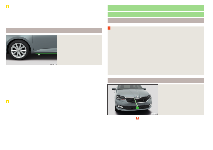
Driving through water

Fig. 202 

Maximum permissible water lev-

el when driving through water

The following instructions must be observed if vehicle damage is to be avoided

when driving through water (e.g. flooded roads).

Therefore, always determine the depth of the water before driving through

water. The water level must not go above the web of the lower beam

» Fig. 202

.

Drive at no more than walking pace, otherwise a wave may form in front of

the vehicle, which could cause the water to enter into the vehicle’s systems

(e.g. the air intake system for the engine).

Never stop in the water, do not reverse and do not switch the engine off.

CAUTION

If water gets into the vehicle’s systems (e.g. the air intake system for the en-

gine) it can cause serious damage to the vehicle!

Oncoming vehicles can generate water waves which can exceed the permis-

sible water level for your vehicle.

Do not drive through salt water, as the salt can cause corrosion. A vehicle

coming into contact with salt water is to be thoroughly rinsed with fresh wa-

ter.

Assist systems

General information

Introduction

WARNING

The assistance systems only serve to support and do not relieve the driv-

er of the responsibility for driving the vehicle.

The increased safety provision, as well as the increased occupant protec-

tion provided by the assistance systems must not tempt you to take risks -

risk of accident!

Adjust the speed and driving style to the current visibility, weather, road

and traffic conditions.

The assistance systems have physical and system-related limitations. For

this reason, the driver may experience some undesired or delayed system

responses in certain situations. You should therefore always be alert and

ready to intervene!

Only enable, disable or set the assistance systems so that you have the

car fully under control in every traffic situation - risk of accident!

Radar sensor

Fig. 203 

Installation location of the radar

sensor

Read and observe   on page 172 first.

The radar sensor (hereinafter on referred to as sensor) uses electromagnetic

waves to capture the traffic situation ahead of the vehicle 

» Fig. 203

.

The sensor is part of the ACC

» page 185

 and Front Assist

» page 190

systems.

172

Driving

-------------------------------------------------------------------------------------------------------------------------------------------------------------

The sensor function may be impaired in the events of one of the following.

The sensor cover is soiled (e.g. with mud, snow etc.).

The area in front of and around the sensor cover is obscured (e.g. by labels,

auxiliary headlights etc.).

When visibility is poor, (e.g. fog, heavy rain, thick snowfall).

If the sensor is covered or dirty, the corresponding message appears in the in-

strument cluster display for the ACC system

» page 190

Malfunctionsor Front

Assist system 

» page 192

Malfunctions.

WARNING

If you suspect that the sensor is damaged, deactivate the ACC system

and Front Assist system

» page 187

» page 192

. Have the sensor checked

by a specialist garage.

A collision or damage in the front or lower area of the vehicle could affect

the sensor function - there is risk of accident! Have the sensor checked by

a specialist garage.

Do not cover the area in front of and around the sensor cover. This can

lead to impaired function of the sensor - risk of accidents!

CAUTION

Remove the snow with a brush and the ice with a solvent-free de-icer.

Braking and stabilisation systems

Introduction

The brake and stabilization systems are automatically activated each time the

ignition is switched on, unless otherwise indicated.
The error display is in Chapter 

» page 37

Warning lights.

WARNING

The general information relating to the use of assistance systems must be

observed 

» page 172,

   in section Introduction.

Stability Control (ESC)

Read and observe   on page 173 first.

ESC improves vehicle stability in critical driving situations (e.g. if the vehicle

starts to skid) by the braking the individual wheels to maintain the direction.
If there is a TCS intervention, the indicator light

 flashes in the instrument

cluster.

Anti-lock brake system (ABS)

Read and observe   on page 173 first.

ABS prevents the wheels locking when braking. Thereby, it helps the driver to

maintain control of the vehicle.
An ABS intervention can be noticed through pulsating movements of the

brake pedal and distinct noises.
When the ABS system is active, do not pump the brakes or lift off the brake

pedal.

Engine drag torque control (MSR)

Read and observe   on page 173 first.

MSR counteracts the tendency of the drive wheels to lock during downshifts

or sudden deceleration (e.g. on icy or an otherwise slippery road surface).
If the drive wheels should lock, then the engine speed is automatically in-

creased. This reduces the braking effect of the engine and the wheels can ro-

tate freely again.

173

Assist systems

-------------------------------------------------------------------------------------------------------------------------------------------------------------

Traction control (TCS)

Fig. 204 

Key for the TCS system

Read and observe   on page 173 first.

The TCS prevents the drive wheels from spinning. TCS reduces the drive pow-

er transmitted to the wheels in the case of slipping wheels. Thereby, for exam-

ple, driving on road surfaces with low grip is made easier.
During a TCS intervention, the indicator light 

 flashes in the instrument clus-

ter.

Deactivation

Press the  

» Fig. 204

 button.

or: On Infotainment, press the 



 button, then tap the function surface  →

ESC system: → ASR off.

During deactivation the warning light lights up in the instrument cluster 

 and

an appropriate message is displayed in the instrument cluster.

Activation

Press the  

» Fig. 204

 button.

or: On Infotainment, press the 



 button, then tap the function surface  →

ESC system: → Activated.

During activation extinguished the warning light 

 is and an appropriate mes-

sage is displayed in the instrument cluster.

The TCS should normally always be enabled. The system should be deactivated

only in the following situations, for example.

When driving with snow chains.

When driving in deep snow or on a very loose surface.

When “rocking a car free” when it has become stuck.

Electronic Differential Lock (EDL and XDS)

Read and observe   on page 173 first.

EDL prevents the turning of the respective wheel of the driven axle. EDL

brakes a spinning wheel if required and transfers the drive power force to the

other drive wheel. Driving becomes easier on road surfaces with different

traction under each wheel of the driven axle.
EDL switches off automatically to avoid excessive heat generation on the

brake of the wheel being braked. Once the brakes have cooled down, there is

an automatic re-activation of EDL.
XDS+ is an extension to the electronic differential lock (EDL). The XDS+ re-

sponds to the release of pressure on the wheels during fast cornering by

means of a braking intervention on the wheel on the inside of the corner on

the driven axle. By decelerating the individual wheels, this prevents the vehicle

from over-steering or understeering. This has a positive effect on the driving

stability and steerability of the vehicle.

Brake Assist (HBA)

Read and observe   on page 173 first.

HBA increases the braking effect and helps to shorten the braking distance.
The HBA is activated by very rapid depression of the brake pedal. To achieve

the shortest possible braking distance, the brake pedal must be applied firmly

until the vehicle has come to a complete standstill.
HBA is automatically switched off when the brake pedal is released.

Hill Start Assist

Read and observe   on page 173 first.

When driving on slopes, Hill Start Assist (hereinafter referred to simply as the

system) allows you to move your foot from the brake pedal to the accelerator

pedal without the vehicle rolling downhill on its own.
The vehicle is braked by the system for about 2 seconds after releasing the

brake pedal.
The system is active as of a 5% slope, if the driver door is closed. The system is

only ever active on slopes when starting off in forward or reverse.

174

Driving

-------------------------------------------------------------------------------------------------------------------------------------------------------------

Multicollision brake (MCB)

Read and observe   on page 173 first.

MCB helps to decrease speed after a collision by means of automatic braking

interventions and to stabilise the vehicle. This reduces the risk of a subsequent

crash due to uncontrolled vehicle movement.
The automatic brake interventions can take place only if the following condi-

tions are met.

There was a front, side and rear-end collision of a certain severity.
The impact speed was greater than approx. 10 km/h.
The brakes, the ESL and other required electrical systems remain function-

al after impact.
The accelerator pedal is not actuated.

Parking aid (ParkPilot)

Introduction

The parking aid (hereinafter simply referred to as the system) uses acoustic

signals on the Infotainment screen when manoeuvring around obstacles in the

vicinity of the vehicle.

WARNING

The general information relating to the use of assistance systems must be

observed 

» page 172,

   in section Introduction.

Moving persons or objects may not be recognised by the system sensors.

Under certain circumstances, surfaces of certain objects and types of

clothing cannot reflect the system signals. There is a danger that such ob-

jects or people may not be recognised by the system sensors.

External noise sources may affect the signals of the system sensors.

There is a danger that obstacles may not be recognised by the system sen-

sors.

Before reversing, make sure that there are no small obstacles, such as

rocks, thin posts, etc., in front of or behind your vehicle. Such obstacles

may not be recognised by the system sensors.

CAUTION

Keep the system sensors 

» Fig. 205

 on page 176 clean and free from snow

and ice, and do not cover them with any objects of any kind, otherwise the

functioning of the system may be restricted.

In adverse weather conditions (heavy rain, water vapour, very low or high

temperatures, etc.), the functioning of the system may be impaired - “incorrect

recognition of obstacles”.

Accessories additionally installed on the vehicle rear, such as bicycle carriers,

can impair the system function.

Settings in Infotainment

Read and observe   and   on page 175 first.

In the Infotainment, in menu 



, tap in the function surface  → Parking and

manoeuvring.

ParkPilot – Settings for the parking aid

Activate automatically – Activate/deactivate the compact parking aid display

(when driving forward)

Front volume – Adjust the volume of the beeps for obstacle detection in front

Front tone setting – Setting the pitch of the beeps for obstacle detection in

front

Rear volume – Set the volume level of the beeps for the rear obstacle detec-

tion

Rear tone setting – Setting the pitch of the beeps for the rear obstacle detec-

tion

Entertainment fading while parking – Lowers the audio volume (e.g. radio vol-

ume) with activated parking aid

175

Assist systems

-------------------------------------------------------------------------------------------------------------------------------------------------------------

Operation

Fig. 205  Installation location of the sensors on the left side of the vehi-

cle: front/rear

Fig. 206 

Sampled areas and range of the

sensors

Read and observe   and   on page 175 first.

The system uses ultrasound waves to calculate the distance between the

bumper and an obstacle. The ultrasonic sensors are, depending on vehicle

equipment,, located in the back or in the front bumper 

» Fig. 205

.

Depending on the equipment, the following system versions are possible

» Fig. 206

.

Variant 1: warns of obstacles in areas 

C

D

.

Variant 2: warns of obstacles in areas 

A

B

C

D

.

Approximate range of sensors (in cm)

Area 

» Fig. 206

Variant 1

(3 sensors)

Variant 2

(7 sensors)

A

-

120

B

-

60

C

160

160

D

60

60

Audible signals

The interval between the acoustic signals becomes shorter as the clearance is

reduced. At a distance of approx. 30 cm a continuous tone starts to sound -

danger area.
The acoustic signals can be set in the Infotainment system 

» page 175

.

Towing a trailer

When towing, or when another accessory is connected to the trailer socket,

only areas 

A

 and 

B


» Fig. 206

 are active in the system.

Note

The signal tones for front obstacle recognition are factory-set to be higher

than for rear obstacle recognition.

Display Infotainment screen

Fig. 207 

Screen display

Read and observe   and   on page 175 first.

Function surfaces and warnings 

» Fig. 207

A

Road display.

176

Driving

-------------------------------------------------------------------------------------------------------------------------------------------------------------

   Depending on the Infotainment type: Switching off park assistant dis-

play.

   Switching audible parking signals on/off.

Change to rear-view camera display .

There is an obstacle in the collision area (the distance to the obstacle

is less than 30 cm). 

 Stop moving in the direction of the obstacle!

There is an obstacle in the road (the distance to the obstacle is great-

er than 30 cm).

An obstacle is located outside of the road (the distance to the obsta-

cle is greater than 30 cm).

System failure (there is no indication of obstacles).

Road display

The road display 

A


» Fig. 207

 indicates the road on which the vehicle would

take the current steering wheel and shift / selector lever position.
The shift lever is in the neutral position and the gear selector is in mode N. the

road display is at the front.

Activation / deactivation

Fig. 208 

System key (option 2)

Read and observe   and   on page 175 first.

Activation

The system is activated when the reverse gear is engaged, or, in vehicles with

variant 2, also by pressing the button  

» Fig. 208

.

When activating, an alarm sounds and the symbol 

 illuminates in the button.

Deactivation

On vehicles with Version 1, the system can be deactivated by moving out of

reverse gear.
For vehicles with variant 2, the system is automatically deactivated by press-

ing the  button or at a speed above 15 km/h (the 

 symbol in the button

goes out).

Displaying an error

If a warning signal sounds for 3 seconds after activating the system and there

is no obstacle close to your car, this indicates a system fault. The fault is also

indicated by the symbol 

 flashing in the button. Seek help from a specialist

garage.

Note

The system can only be activated with the  button at a speed of below 15

km/h.

Automatic system activation when moving forward

Fig. 209 

Infotainment screen: Display

with automatic activation

Read and observe   and   on page 175 first.

The automatic system activation occurs when moving forward at a speed be-

low 10 km/h when the vehicle approaches an obstacle.
After activation, the following is shown in the left pane of the Infotainment

screen 

» Fig. 209

.

Acoustic signals are sounded as of a distance from the obstacle of around

50 cm.
The automatic display can be activated / deactivated in the Infotainment sys-

tem 

» page 175

.

177

Assist systems

-------------------------------------------------------------------------------------------------------------------------------------------------------------

Rear traffic alert and wizard for “Blind spot”Monitoring

Introduction

Fig. 210 

Installation location of the radar

sensors

The Rear Traffic Alert and Wizard for “blind spot” monitoring works based on

the information from the radar sensors in the rear bumper 

» Fig. 210

. The radar

sensors are not visible from the outside.

Rear Traffic Alert

The Rear Traffic Alert (hereinafter referred to as system) warns when leaving a

parking space from a transverse parking space about any approaching vehi-

cles.

Wizard for “blind spot”monitoring

The wizard for“blind spot monitoring” (hereafter referred to as system) draws

attention to vehicles travelling in the same direction in the next lane in the so-

called blind spots.
The “blind spot” is an area that is not easily visible in a rear-view mirror or even

directly from the vehicle.

WARNING

Please take note of the general points relating to the use of assistance sys-

tems 

» page 172,

   in section Introduction.

WARNING

In the case of a collision or damage to the rear of the vehicle, the function

of the systems may be affected - risk of accident! Have the vehicle

checked by a specialist garage.

Do not cover the sensor area - the function of the systems could be limi-

ted.

Remove snow, ice and such obstacles from the sensor environment im-

mediately.

WARNING

The wizard for “blind spot”monitoring is limited by physical and system-re-

lated limits. Therefore, in the following situations the system can be de-

layed in drawing attention (or not at all) to a vehicle in the next land.

When a vehicle is approaching at a very high speed.

When passing through a very sharp curve or a roundabout.

CAUTION

If a trailer or other accessory is to be connected to the trailer socket, then

the two systems are not available.

In adverse weather conditions (heavy rain, water vapour, very low or high

temperatures, etc.), the system function may be limited - “failure to recognise

a vehicle”.

Accessories additionally installed on the vehicle rear, such as bicycle carriers,

can impair the system function.

178

Driving

-------------------------------------------------------------------------------------------------------------------------------------------------------------

Rear Traffic Alert- Operation

Fig. 211  Infotainment screen: warning indicator / driving situation

Read and observe   and   on page 178 first.

With the ignition switched on, the area next to and behind the vehicle is moni-

tored by the radar sensors of the system. If an approaching vehicle is detected

from the rear of the vehicle 

» Fig. 211

, the system warns of this fact.

Warning - vehicles with parking aid

You will hear a continuous tone and one of the following warning levels ap-

pears on the Infotainment screen 

» Fig. 211

.

An oncoming vehicle is detected. Do not continue driving backwards and

check around the vehicle.
A vehicle in the collision region is detected. Do not continue reversing 

.

Warning - vehicles without parking sensors

An acoustic signal is sounded and information for the driver to observe the

traffic behind is shown in the instrument cluster.

CAUTION

If a collision risk is detected, no automatic system-related braking takes place.

Wizard for “Blind Spot”Monitoring - Operation

Read and observe   and   on page 178 first.

At a speed over 15 km/h, the area alongside and behind the vehicle is moni-

tored by the system. At the same time, the distance and the difference in

speed between your vehicle and the other vehicles in the monitored area can

be measured.

A

B

When driving, the sensors monitor an area to the left and right to the extent of

a normal lane width.
If a vehicle is detected in the “blind spot” area, the system indicates this vehi-

cle by the warning light 

 in the exterior mirror.

System limitation

The system is unable to recognise the specific lane width by means of sensors.

Therefore this can e.g. in the following cases respond to a vehicle in a further

lane.

When driving on a road with narrow lanes or on the lane edge.

Driving around a bend.

The system may also respond to objects on the roadside such as crash barri-

ers, noise barriers or similar objects.

Wizard for “Blind Spot”Monitoring - driving situations and warnings

Fig. 212  Driving situation / indicator light in the left outside mirror indi-

cates the driving situation

179

Assist systems

-------------------------------------------------------------------------------------------------------------------------------------------------------------

Fig. 213  Driving situation / indicator light in the right outside mirror indi-

cates the driving situation

Read and observe   and   on page 178 first.

In the following situations, the indicator light in the outside mirror indicates a

vehicle in the “blind spot”.

Your vehicle 

B

 is being overtaken by vehicle 

A

» Fig. 212

.

Your vehicle 

C

 is overtaking vehicle 

D

 at a speed of max. 10 km high-

er

» Fig. 213

. If the speed during the overtaking is even higher, then there is

no warning by the warning light.

The warning display is always in the exterior mirror on the side of the vehicle

where a vehicle is detected in the “blind spot”.
The greater the speed difference between the two vehicles, the earlier the

warning (by means of the warning light) regarding the vehicle that is overtak-

ing you takes place.

Two warning levels

 light up - a vehicle has been detected in the “blind spot”.

 flash - a vehicle has been detected in the “blind spot” and the turn signal is

switched on.

Note

The brightness of warning light 

 is dependent on the vehicle lighting setting.

With the low or high beam on the brightness of the light will be lower.

Activation / deactivation

Read and observe   and   on page 178 first.

The activation or deactivation of the system can be carried out in one of the

following ways.

In the instrument cluster display 

» page 50

Menu item Assist systems.

In the infotainment system, in menu 



/  →  → Driver assistance (applies to

the wizard for “blind spot” monitoring).

In the infotainment system, in menu 



/  →  → Parking and manoeuvring (Ap-

plies to Rear Traffic Alerts).

After switching off and switching on the ignition, depending on the setting pri-

or to switching off the ignition, the systems remains activated / deactivated.

Note

During activation of the “blind spot” monitoring wizard, the 

 warning lights

light up in the two exterior mirrors.

Malfunctions

Read and observe   and   on page 178 first.

If the systems are not available, an appropriate message appears in the display

of the instrument cluster.

Sensor covered / dirty

If the sensor is dirty or covered, a message indicating that there is no sensor

view appears. Clean or remove the obstructing object from the sensor envi-

ronment 

» Fig. 210

 on page 178.

Systems unavailable

If the systems are unavailable, a message regarding unavailability appears. Stop

the vehicle, switch off the engine and then start it again. If the systems are still

not available, seek the assistance of a specialist garage.

System fault

In the case of a system fault, an error message appears. Seek help from a spe-

cialist garage.

180

Driving

-------------------------------------------------------------------------------------------------------------------------------------------------------------

Reversing camera

Introduction

The reversing camera (hereinafter the system) helps the driver to park and ma-

noeuvre the vehicle by displaying the area behind the vehicle on the Infotain-

ment screen (hereinafter only referred to as the screen).

WARNING

The general information relating to the use of assistance systems must be

observed 

» page 172,

   in section Introduction.

The camera may not be soiled or obscured, otherwise the system func-

tion will be significantly affected - there is a risk of accident. For informa-

tion on cleaning 

» page 205

.

CAUTION

The camera image is distorted by contrast with eyesight. For this reason, the

screen display is only of limited use for estimating distances to vehicles be-

hind.

Some items, such as narrow columns, chain link fences or lattice, may not be

represented adequately in terms of screen resolution.

In a crash or damage the vehicle's rear camera can possibly deviate from the

correct position. If this is the case, have the sensor checked by a specialist ga-

rage.

Note

The camera is equipped with a cleaning system. The spraying is carried out au-

tomatically when the rear window is sprayed.

Operation

Fig. 214  Installation location of the camera / scanned area behind the

vehicle

Read and observe   and   on page 181 first.

The camera for capturing the area behind the vehicle is in the boot lid handle

» Fig. 214

.

Area behind the vehicle 

» Fig. 214

Detection range of the camera
Area outside the detection range of the camera

The system can assist the driver when parking and manoeuvring under the fol-

lowing basic conditions.

The ignition is switched on.
Reverse gear is engaged.
The luggage compartment lid is completely closed.
The vehicle is travelling at less than 15 km/h.
The area behind the vehicle is clearly visible.
The selected parking / manoeuvring area is clear and even.

Note

The screen display can be interrupted by pressing the symbol button 

» Fig. 208

 on page 177.

After disengaging reverse gear, automatic screen display of the parking aid is

carried out (variant 2) 

» page 176

.

A
B

181

Assist systems

-------------------------------------------------------------------------------------------------------------------------------------------------------------

Guidelines and function surfaces

Fig. 215  Infotainment screen: Orientation lines / function interfaces

Read and observe   and   on page 181 first.

On the screen, orientation lines are shown along with the monitored area be-

hind the vehicle.
Distance of the orientation lines behind the vehicle 

» Fig. 215

The distance is about 40 cm (safety distance limit).
The distance is about 100 cm.
The distance is about 200 cm.

The distance may vary slightly depending on the load of the vehicle and the

road inclination.
The distance between the side lines corresponds approximately to the vehicle

width including mirrors.
Function surfaces 

» Fig. 215

Depending on the Infotainment type: Turns off the display of the area

behind the vehicle
Screen settings – brightness, contrast, colour

Switching audible parking signals on/off

Enabling and reduced park assistance display

Change to park assistance display

CAUTION

The objects shown on the screen can be closer or even further away than they

appear. This is especially the case in the following situations.

Protruding objects, such as the rear of a truck and the like.

A
B
C

  

  

  

When driving from a horizontal surface into a slope or a depression.

When driving from a slope or a depression onto a horizontal surface.

Cruise Control System

Introduction

The Cruise Control System (CCS) maintains a set speed without you having to

actuate the accelerator pedal. The status where the CCS maintains the speed

is referred to hereinafter as the control.

WARNING

The general information relating to the use of assistance systems must be

observed 

» page 172,

   in section Introduction.

After pressing the clutch pedal, no interrupted control occurs! For exam-

ple, if a different gear is engaged and the clutch pedal is released, control is

continued.

Operation

Fig. 216  MAXI DOT display (monochrome): Examples of status displays

the CCS

182

Driving

-------------------------------------------------------------------------------------------------------------------------------------------------------------

Fig. 217  Segment display: Examples of status displays the CCS

Read and observe   on page 182 first.

CCS status displays 

» Fig. 216

» Fig. 217

Speed set, but control is inactive.
Control is active.
No speed set.
System fault - seek assistance from a specialist garage immediately.

Basic requirements for starting the control

The CCS is activated.
On vehicles with a manual transmission, the second gear or higher is en-

gaged.
On vehicles with an automatic transmission, the selector lever is in the

D/S position or in the Tiptronic position.
The current speed is higher than 20 km/h.

This, however, is only possible to the extent permitted by the engine output

and braking power of the vehicle.

WARNING

If the engine output or engine braking effect is insufficient to maintain the

set speed, the driver must assume control of the accelerator and brake

pedals!

Operation description

Fig. 218 

Cruise control system controls

Read and observe   on page 182 first.

Overview of the control elements of the CCS 

» Fig. 218

A



Activate CCS (control deactivated)




Interrupt control (sprung position)




Deactivate CCS (delete set speed)

B



Take control again

a)

 / Increase speed

C



Start control / reduce speed

D



Switch between GRA and Speed Limiter

a)

If no speed is set the current speed is adopted.

Once the controls are activated, the CCS maintains the vehicle at the set

speed; the indicator light 

 lights up in the instrument cluster.

Controls are automatically interrupted if any of the following occur.

The brake pedal is operated.

When one of the brake assist systems (e.g. ESC) intervenes.

Through an airbag deployment.

By pressing button 

D


» Fig. 218

.

WARNING

Always deactivate the cruise control system after use to prevent the sys-

tem being enabled unintentionally.

The control does not resume if the set speed is too high for the existing

traffic conditions.

183

Assist systems

-------------------------------------------------------------------------------------------------------------------------------------------------------------

Note

During control, speed can be increased by pressing the accelerator pedal. Re-

leasing the accelerator pedal will cause the speed to drop again to the set

speed.

By pressing the button 

D


» Fig. 218

 during the control procedure this is can-

celled and the Speed Limiter is activated.

Speed limiter

Introduction

The Speed Limiter limits the maximum driving speed to the set speed limit.
The speed limit can only be exceeded by depressing the accelerator pedal fully.
The condition in which the speed limiter prevents a set speed limit from being

exceeded is referred to hereinafter as Regulation.

WARNING

The general information relating to the use of assistance systems must be

observed 

» page 172,

   in section Introduction.

Operation

Fig. 219  MAXI DOT display (monochrome): Examples of Speed Limiter

status displays

Fig. 220  Segment display: Examples of Speed Limiter status displays

Read and observe   on page 184 first.

Status displays of the speed limiter 

» Fig. 219

» Fig. 220

Speed limit set, but regulation is inactive.
Control is active.
No speed limit set.
System fault - seek assistance from a specialist garage immediately.

Basic requirements for starting the control

The Speed Limiter is activated.
The current speed is higher than 30 km/h.

184

Driving

-------------------------------------------------------------------------------------------------------------------------------------------------------------

Operation description

Fig. 221  Operating elements of the speed limiter: Vehicle with Speed

Limiter / vehicle with GRA and Speed Limiter

Read and observe   on page 184 first.

Overview of the control elements of the speed limiter 

» Fig. 221

A



Activate Speed Limiter (regulation deactivated)


For vehicles with GRA and Speed Limiter, the GRA is activated by

the switch in the  position by being adjusted. The activation of

the speed limiter occurs only after pressing the button 

D

.




Interrupt control (sprung position)




Speed Limiter disable (set limit delete)

B



Take control again 

a)

/ increase speed - press (in increments of 1

km/h), hold (in increments of 10 km/h)

C



Start control/ reduce speed - press (in increments of 1 km/h), hold

(in increments of 10 km/h)

D



Switching between CCS and speed limiter

a)

If no speed limit is set, the current speed is set as the speed limit.

After starting the system, the current speed is set as the speed limit, the warn-

ing light 

 lights up in the instrument cluster.

Exceeding the speed limit during the regulation

If, during the setting, it is necessary to exceed the speed limit (e.g. to over-

take), the accelerator pedal must be pressed fully.
When exceeding the speed limit (e.g. driving down a hill), an acoustic signal

sounds and the warning light 

 flashes in the instrument cluster.

The regulation is resumed once the speed has fallen below the set limit.

Note

By pressing the button 

D

 during the control this is cancelled and the CCS is

activated.

Adaptive Cruise Control (ACC)

Introduction

The Adaptive Cruise Control (hereinafter referred to as ACC) maintains the set

speed and at the same time the distance to the vehicle ahead without the ac-

celerator or brake pedal being pressed.
The front of the vehicle and the distance to the vehicle ahead is monitored by

a radar sensor 

» page 172

.

The state in which the ACC maintains the speed or the proximity is described

as control from here on.

WARNING

The general information relating to the use of assistance systems must be

observed 

» page 172,

   in section Introduction.

The driver must always be ready to take over the operation of the accel-

erator and brake pedal.

The ACC does not react when approaching a stationary obstacle, such as

traffic jams, vehicle breakdowns or vehicles waiting at a traffic light.

The ACC does not respond to crossing or oncoming objects.

If the ACC does not decelerate fast enough, immediately apply the vehi-

cle's foot brake.

WARNING

For safety reasons, do not use the ACC under the following conditions.

When driving in turning lanes, motorway exits or construction sites, to

avoid an unwanted acceleration to the stored speed.

When visibility is poor, (e.g. fog, heavy rain, thick snowfall).

When road conditions are poor (e.g. ice, slippery road, gravel, dirt road).

Driving into “sharp” corners or in steep gradients / on steep inclines.

185

Assist systems

-------------------------------------------------------------------------------------------------------------------------------------------------------------

WARNING (Continued)

When driving through places where metal objects (such as metal build-

ings, railway tracks, etc.) can be found.

When driving through very divided and enclosed spaces (such as large-

capacity garages, car ferries, tunnels and the like.).

Note

The ACC is designed primarily for use on motorways.

The ACC reduces the speed by automatically releasing the accelerator or by

means of a braking procedure as appropriate. If the brakes are used for an au-

tomatic speed reduction at any moments, then the brake light illuminates.

In case of failure of more than one brake light on the vehicle or on the con-

nected trailer, the ACC becomes unavailable.

The control automatically cancels the engagement of the brake supportive

assistance systems (e.g. ESC) or when the maximum permitted engine speed is

exceeded.

Settings in Infotainment

Read and observe   on page 185 first.

In the Infotainment, in menu 



, tap in the function surface  → Driver assis-

tance.

ACC (adaptive cruise control) - Setting for the ACC

Driving progr.: - Sets the vehicle acceleration when the ACC is activated

Last distance selected - Last selected distance level on/off

Distance: - Set the distance to the vehicles ahead

Operation

Fig. 222  Instrument cluster display: Examples of ACC displays

Fig. 223  Instrument cluster display: Examples of ACC status displays

Read and observe   on page 185 first.

The ACC makes it possible to set a speed of 30-160 km/h as well as to set the

distance from the vehicles in front.
The ACC can detect a vehicle that is up to approx. 120 m ahead using the radar

sensor.
ACC displays 

» Fig. 222

Vehicle detected (control active)
Line showing the displacement of the distance when setting 

» page 188

,

Setting the distance
Set distance to the vehicle ahead
Vehicle detected (control deactivated)

1

2

3
4

186

Driving

-------------------------------------------------------------------------------------------------------------------------------------------------------------

Status conditions of the ACC 

» Fig. 223

Control deactivated.
Control activated - no vehicle detected.
Regulation deactivated - no speed stored.
Control activated (vehicle detected).

Note to reduce speed

If the delay of the ACC is insufficient in relation to the vehicle in front, the

warning light

 lights up in the instrument cluster and the display shows a

message to engage the brake pedal.

Note

Some ACC notifications in the display of the instrument cluster may be hidden

by notifications for other functions. An ACC notification automatically appears

for a brief moment when there is a change in status of the ACC.

Automatic stopping and starting

Read and observe   on page 185 first.

Vehicles with an automatic transmission can decelerate to a complete stop

and start moving again using the ACC.

Decelerate to a complete stop

If a vehicle ahead decelerates to a standstill, the ACC will also decelerate your

vehicle to a complete stop.

Starting to drive again after a holding period

As soon as the vehicle ahead starts moving again after a holding period, your

vehicle will also move and the speed will continue to be controlled. Control is

automatically disconnected in case of longer holding periods.

Summary of operations

Fig. 224  Operating lever

Read and observe   on page 185 first.

Overview of ACC functions operated with the lever 

» Fig. 224

1



Activate ACC (control deactivated)

2



Start control (resume) / increase speed by 1 km/h at a time

(sprung position)

3



Interrupt control (sprung position)

4



Deactivate ACC

5



 

Increase speed by 10 km/h at a time

6



 

Decrease speed by 10 km/h at a time

A

  Set proximity level

B



Start control / reduce speed in increments of 1 km/h

If the lever is set from the position  directly into the sprung position 

the current speed is stored and the control process is started.

187

Assist systems

-------------------------------------------------------------------------------------------------------------------------------------------------------------


Content      ..     9      10      11      12     ..