Dacia SuperNova (engine E7J). Manual - part 40
 

  Index      Dacia     Dacia SuperNova (engine E7J) - service repair manual 2004 year


Search            


Content   ..  38  39  40  41   ..


Dacia SuperNova (engine E7J). Manual - part 40


 E7J-A-2/60 ENGINE

17

IGNITION AND INJECTION

17 - 70

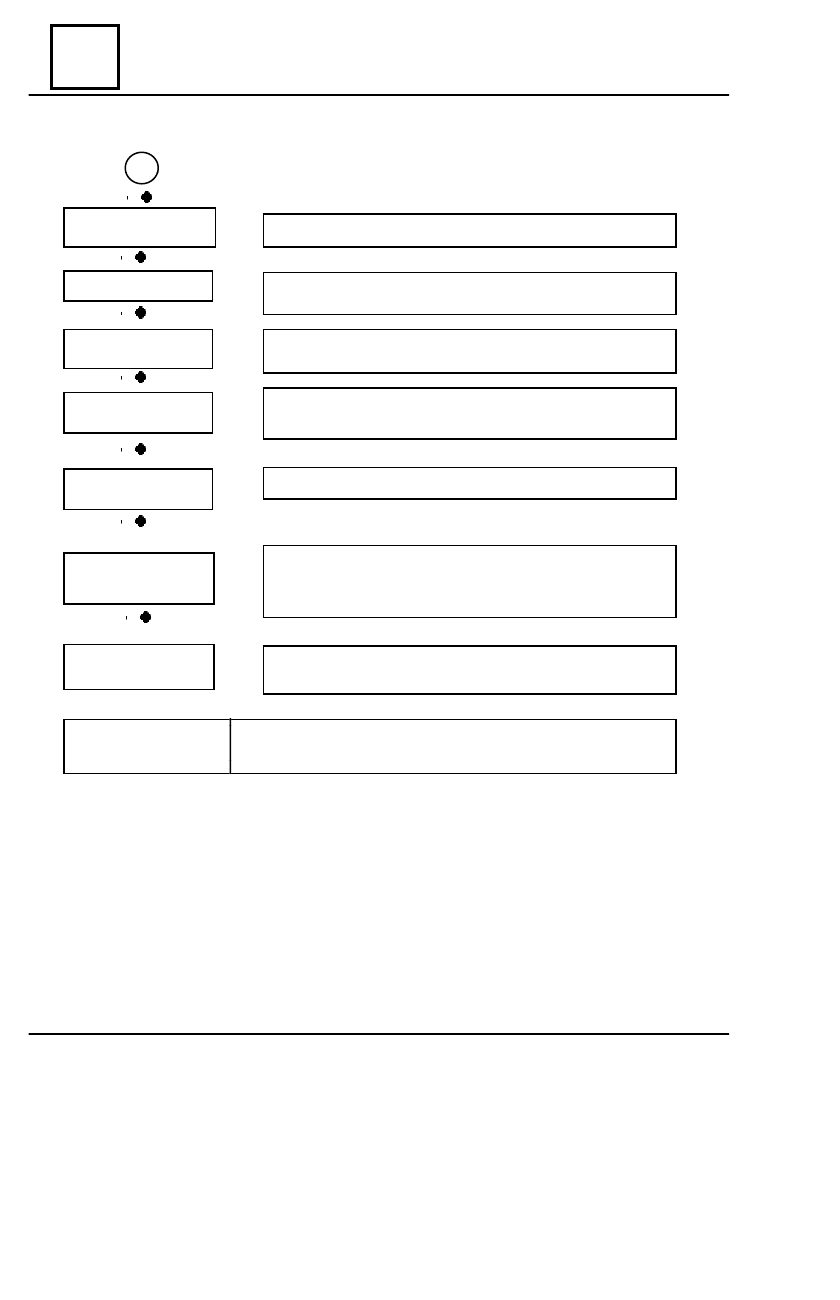
DIAGNOSING-BREAKDOWN LOCALIZATION ALGORITHM

Check if the clapper body is not clogged.

Check if there are cases of lack of watertightness (noise)
on the power-brakes.

 Connect the tester “CLIP” and do the test corresponding
to the check-up of the rotation signal.

Check if the spurs, the brake cylinders and the wheel ball-
rings are not seized-up.

Check the body of
the clapper

♦

Check the power-brakes

Check the engine
flywheel

Check the running
train

Check the cooling
of the engine

♦

♦

♦

Check if there is enough engine cooling.

♦

Check the canister
draining valve

Disconnect the tube between the draining valve and the in-
take collector and strangle it up. If the disturbances disap-
pear, the cause was the draining valve.

Check the engine
compression

 Connect the “CLIP TEHNIC” device to do this test in accor-
dance with the usual manner of work.

AFTER REPAIR

Erase the defects memorized. If there are no other problems,
erase the parameters memorized by the calculator.

♦

♦

A

19 - 1

19

COOLING - EXHAUST  - FUEL TANK

QUANTITY AND QUALITY OF COOLING LIQUID


TYPE ENGINE


 QUANTITY 

(

L

)           C

ALITATE


PECULIARITIES


  E7J                       6


     Anti-freeze type D      Protection up to  -40

0

C

           GLACEOL RX

THERMOSTAT


TYPE ENGINE


   START OF OPENING 


(0C)       END OF OPENING 


(0C)


     DRIVE 

 (

MM

)

        E7J

   89

      101

   7,5


 CHARACTERISTICS

19 - 02

FILLING  AND  DRAINING

The heating radiator does not have a tap.
The circulation of the cooling liquid is done continuosly within the heating radiator, which con-
tributes to the heating of the engine.

F

ILLING

The tightening of the emptying stopper is checked.
The draining screw placed on the tube between the engine and the air-conditioning radiator is
taken off.
The circuit is filled through the hole of the de-gassing pot.
The draining screw is fastened when the liquid flows in a continuous jet.
The engine is set into motion (2500 rot/min).
The level is adjusted for approx. 4 minutes.
The stopper of the de-gassing pot is closed.

D

RAINING

The engine is let to run for 10 minutes at 2500 rot/min until the motor-ventilator starts (i.e. the
time for the automatic de-gassing).
Check if thelevel of the liquid is close to “Max”.
Do not open the draining screw when the engine is running.
Fasten again the stopper of the de-gassing pot with the engine still hot.


 FILLING  AND  DRAINING

19

COOLING - EXHAUST  - FUEL TANK

1.

CHECKING WATERTIGHTNESS OF CIRCUIT

The MS 554-01 adapter is mounted instead of the valve of the de-gassing pot.
The MS 554-07 device is connected to the adapter.
The engine is heated, and then stopped.

the pump is used in order to put the circuit under pressure.

The pumping is stopped at a value 0.1 bar smaller than the tare value of the valve (1.2 bar).
The pressure must not go down; otherwise, the leak is looked for.
The junction of the device for cooling system decompression is progressively unscrewed,

then the apparatus is taken off and the valve of the de-gassing pot, equipped with a new fitting,
is mounted.

2.

CHECKING WATERTIGHTNESS OF CIRCUIT

The MS 554-06 device, then the pressure in the circuit is reestablished; this pressure must

become stable at the tare value of the valve with the control tolerance of +/-0.1 bar.

The tare value of the valve of the de-gassing pot: 1.2 bar.

19

COOLING - EXHAUST  - FUEL TANK


 CONTROL

19 - 03


Content   ..  38  39  40  41   ..