Dacia Solenza (engine E7J). Manual - part 144


  Index      Dacia     Dacia Solenza (engine E7J) - service repair manual 2004 year


Search            


Content   ..  142  143  144  145   ..


Dacia Solenza (engine E7J). Manual - part 144


82

ACCOUSTIC WARNING - ANTI STARTING

82 - 33

Diagnostic

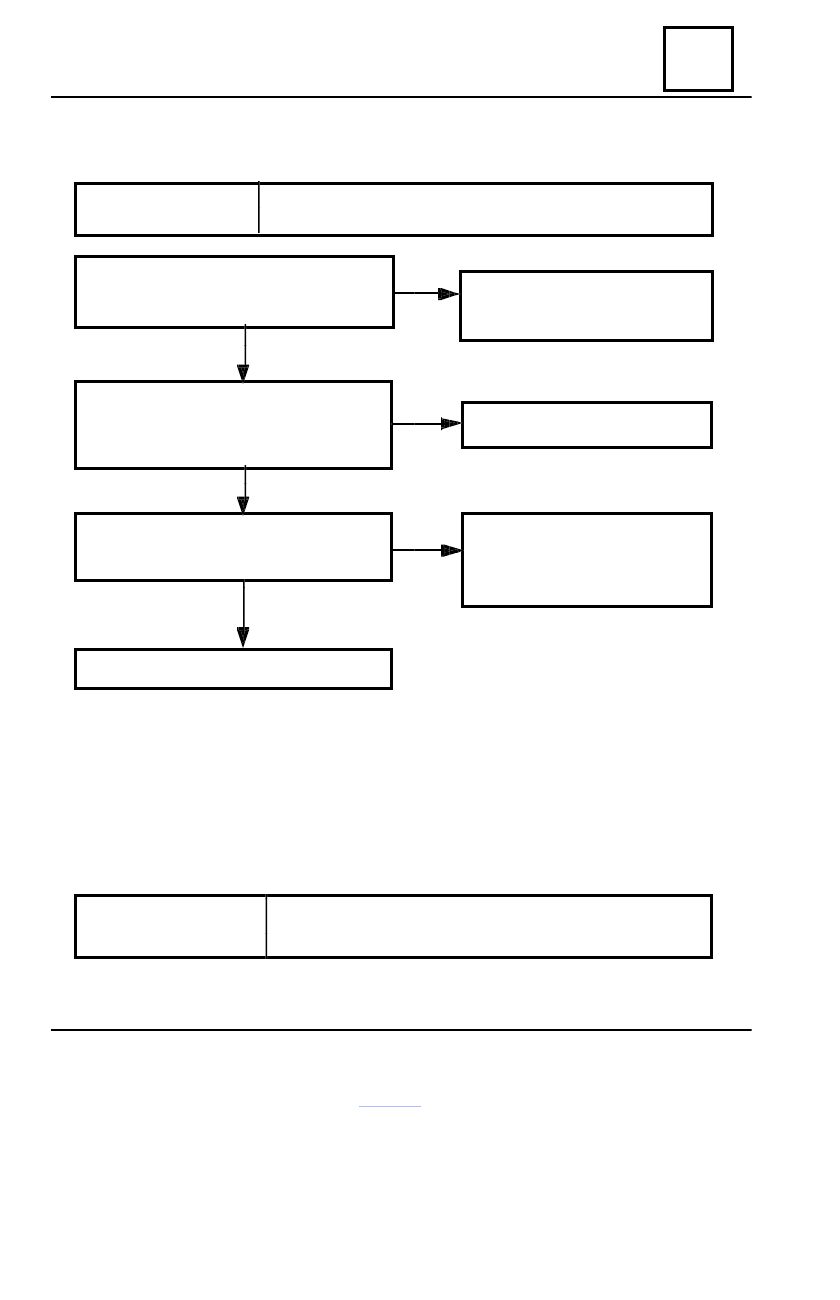
ALP7.  UNLOCKING DOORS NOT OPERATING BY RF REMOTE CONTROL

RECOMMENDATION

Check the absence of failures with the CLIP tester.
If there are memorised failures, these must be repaired.

Are the states 11G and 11D becoming
ACTIVE when the RF  remote control is
activated?

See the treatment of the states 11G
and 11D cf. chapter “Diagnostic”.

No

Check the fuse F03 condition from the cockpit
fuse box.
Is it good?

Replace the fuse.

No

Yes

Yes

See the treatment of the failure

“Doors blocking contact” and the

state 14 G cf. chapter

“Diagnostic”.

See ALP6.

Yes

No

AFTER REPAIRING

Perform a conformity checking.
Check the operation of the anti starting system.

Activate the doors’ locking switch from the
dashboard.
Are the doors blocking/ unlocking ?

82

ACCOUSTIC WARNING - ANTI STARTING

82 - 34

Diagnostic

ALP 8.  TURNING LIGHTS DO NOT SWITCH ON AT THE BLOCKING /
UNLOCKING OF THE DOORS

RECOMMENDATION

Check the absence of the failures with the CLIP tester.
If there are failures, fix them first.

Check if the synchronisation of the RF remote control and the E.C.U. decoder has been
performed.
Are the turning lights functioning normally at the activation of the signalling switch ?

Check the continuity and the isolation
related to the mass and the  +12 V of the
electric layout:
E.C.U. decoder             FLASH relay
             Pin B3              pole 2
Is it correct?

Repair the signalling system.
Check the fuse F03 and F04.

Fix the electric layout.

Check the fuse F02 condition from the cockpit
fuse box.
Is it good?

Replace the fuse.

Disconnect the FLASH relay. Supply with
+12, the pole 4 of the relay. Are the left turning
lights turning  on?  Supply with +12 V the pole
5 of the signal relay. Are the right/left turning
lights turning on?

Repair the electric layout from
poles 4 and 5 of the FLASH relay.

Replace the FLASH relay.

AFTER REPAIRING

Perform a conformity checking.
Check the operation of the anti starting system.

No

No

No

Yes

Yes

Yes

Yes

No

82

ACCOUSTIC WARNING - ANTI STARTING

82 - 35

Diagnostic

No

AFTER REPAIRING

Perform a conformity checking.
Check the operation of the anti starting system.

ALP9.  THE CEILING LAMP DOES NOT SWITCH ON AT THE BLOCKING /
UNLOCKING OF THE DOORS OR IT REMAINS PERMANENTLY TURNED ON

RECOMMENDATION

Check the absence of failures with the CLIP tester.
If there are memorised failures, fix them first.

Check if the doors are locked?

The ceiling lamp was in

the position “permanently

lighting”?

Normal

operation.

Yes

Yes

Unlock the doors with the RF remote control.
The ceiling is in the position “ceiling delayed
lighting ”.
Has the ceiling lamp turned  on?

Check the isolation of the wiring related
to the mass on the line pinA1.
 decoder        pin 3 ceiling lamp.

After 15 seconds, the ceiling lamp will
turn off.
Normal operation.

Was the E.C.U. decoder configured “With
ceiling delayed lamp”?

Configure the E.C.U. decoder with
the CLIP  tester.

Check the continuity on the line
E.C.U. decoder pin A1            pin 3 ceiling
lamp.
Is the line good?

Repair .

Check the ceiling lamp bulb.

No

No

No

Yes

Yes

Yes

No

82

ACCOUSTIC WARNING - ANTI STARTING

82 - 36

Diagnostic

THE CONFORMITY CHECKING

Next, the checking of different states and configurations of the anti starting system is to be

performed.

RECOMMENDATION

In case of finding some failures at the diagnostic by means of
the CLIP tester, analyse them based on the diagnostic (ALP)
corresponding to the respective failure.

Crt.

Function

State/ configuration

 Observations

Nr.

1. Conformity E.C.U decoder. Computer identification

Display of the E.C.U.
decoder item.

2. Remote control type

2G = remote control

IR = infrared

configuration

RF = radio frequency

3. Ceiling delayed lamp

Without ceiling delayed lamp or Validation on the blue button
with ceiling delayed lamp

on CLIP  screen.

4. Key programming

3G = configuration key

With one or 2 keys.

programming

5. Configuration petrol/ diesel 3D = configuration coded diesel Without = for petrol engine

electric valve.

or diesel without electric
valve.

6. Forced starting protection

9D = forced protecting mode

ACTIVE = only after
validation on the blue button.

7. Anti starting state

10G = anti starting

ACTIVE = with the contact
taken off or after 10 seconds
from the contact taken off.

8. Key  presence

8D = key present

ACTIVE  at the setting on
the contact if there is a
coded key.
REMARK:  the states 8D,
9D, 10 D must be ACTIVE
at a correct operation.

9. Code key receiving

9D = received key code

ACTIVE at the setting on
the contact if the key is
coded in a good format.

10. Correct key code

10D = right key code

ACTIVE at the setting on
the contact if the key is
coded in a good format and
has the correct code.
REMARK: after the analyse
of the states 8D, 9D, 10 D
the contact will be set on
when the LED indicator
blinks ( ACTIVE anti
starting).


Content   ..  142  143  144  145   ..