Dacia Pick-Up 1304/1305/1307. Manual - part 120


  Index      Dacia     Dacia Pick-Up 1304/1305/1307 (Engine F8Q) - service repair manual 2004 year


Search            


Content   ..  118  119  120  121   ..


Dacia Pick-Up 1304/1305/1307. Manual - part 120


AIR  CONDITIONING

62

62 - 8

Compressor  is absorbing the vapors coming from the evaporator at low pressure and tem-

perature, is compressing them and convey the gas at high temperature and pressure to the con-
denser.

The compressor is type Harrison V5, alternating, with pistons and variable cylinders capacity.
Compressor oil used PAG SP 10
Quantity of compressor oil used 265 cmc
The compressor is mounted on the left side of the engine block by means of two supports.

ATTENTION !

During handling the compressor oil, reduce to minimum the oil contact with the air,

which contains moisture.

     D

ISMO UNTING

Disconnect the battery.
Drain the refrigerant circuit.
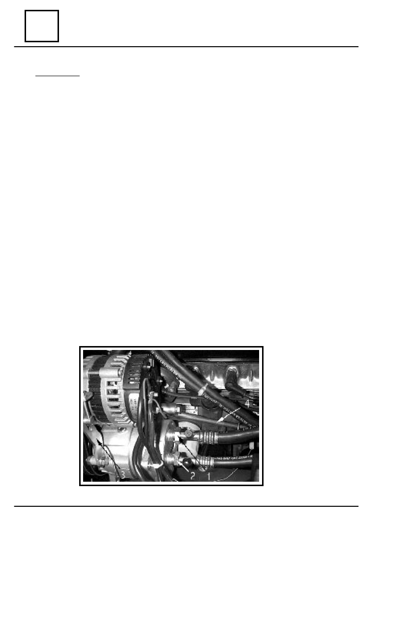
Disconnect the pipes (1) and (2) from the compressor.
Dismount the tensioning clip (3) and the alternator belt.
Disconnect the electric connectors of the alternator and the electric connector of the com-

pressor.

Dismount the alternator attachment screw on the support and detach the alternator.
Dismount the compressor tie rod (4).
Dismount the compressor attachment screws on supports.
Dismount the compressor.

COMPRESSOR

AIR  CONDITIONING

62

62 - 9

COMPRESSOR

R

EMOUNTING

Position the compressor on the attachment supports.
Tighten the compressor on the supports, by means of 3 screws, which are to be initial screwed

in the following order : front upper left, rear lower right, front lower left.

Position and tighten the tie rod on the compressor upper support and on the cylinders hous-

ing.

Screw and tighten at the required moment the compressor attachment screws in the following

order : front upper left, front lower left, rear upper right, rear lower right
(3,5 daNm).

Tighten at the required moment the tie rod attachment screw on the cylinder housing (3,5

daNm).

Mount and tension the alternator belt by acting upon the tightener screw (see chapt.

” Belts tightening checking and tensioning “), then lock it, by tightening the tightener nut at the
required moment (3,5 daNm).

Tension the alternator belt (see chapt.”Belts tightening checking and tensioning “) and tighten

at the required  moment (1,25 daNm) the alternator clamp attachment nut. and the clamp for
alternator belt tightener.

Tighten at the required moment the alternator attachment screw on the support

(2,4 daNm).

Mount the pipes to the compressor and tighten them  at the required moment (2,5 daNm).

ATTENTION !

The compressor – evaporator pipe of  ˚”, is the suction pipe, and the compressor –

condenser pipe of 13/32 ”, is the discharging pipe ( in case mounting is not correct, the
system is not working).

Fill the refrigerant circuit and check the climate control system operation.

NOTE :  When compressor is replaced, obligatory replace also the tank filter.

AIR  CONDITIONING

62

62 - 10

D

ISMO UNTING

Dismount the compressor (see “ Compressor replacement “).
Dismount the upper support.
Dismount the lower support.

R

EMOUNTING

Position the lower support (1) of the compressor on the cylinder housing and initial tighten its

attachment screws.

Position the upper support (2) of the compressor on the cylinder head and initial tightening

its attachment screws.

Position adjustment device MOT 556 on the upper and lower supports and slightly tighten its

attachment screws on the supports.

Tighten at the required moment (1,9daNm) the upper support attachment screws in the following

order: lower left, upper right.

Tighten at the required moment the lower support attachment screws in the following order:

upper left (3 daNm), lower left (1,9 daNm), upper right (3,5 daNm).

Dismount the adjustment device.
Perform the  other operations as dismounting in the reverse order.
Tension the compressor  belt.
Tension the alternator  belt.
Fill the refrigerant circuit and check the climate control operation.

1

2

MOT 556

 COMPRESSOR

 COMPRESSOR SUPPORTS

AIR  CONDITIONING

62

62 - 11

Evaporator has the purpose to transfer to the refrigerant liquid the air heat, which is passing

through it.

The cooled air, is so conveyed in the  passengers compartment, progressively reducing the

temperature.  The refrigerant fluid which goes into the evaporator, absorbs the passengers
compartment heat, cycled transmitted by the GMV-AC at constant temperature and is trans-
forming it from liquid into vapors.

At the inlet refrigerant is liquid at the outlet in G.M.V. – AC it has changes into gas.
The evaporator consists of a package with slotted aluminum plates, separated by an empty

“U- shape” space, where the refrigerant fluid flow is pushed.

The evaporator is mounted on the iron plate, in the right side, under the dashboard, right side,

under the dashboard.

D

ISMO UNTING

Disconnect the battery.
Drain the refrigerant circuit
Dismounting the dashboard.
Remove anti-condense sealing material.
Disconnect the pipes evaporator – compressor and evaporator – tank filter.
Disconnect the connector of the evaporator GMV.
Dismount the thermostatic expansion valve.
Disconnect the air flow pipes.
Dismount the front attachment nuts (1) and (2) of the evaporator unit.
Dismount the evaporator attachment screw (3) on the right front pillar.
Dismount the evaporator.

EVAPORATOR


Content   ..  118  119  120  121   ..