Dacia Pick-Up 1304/1305/1307. Manual - part 59


  Index      Dacia     Dacia Pick-Up 1304/1305/1307 (Engine F8Q) - service repair manual 2004 year


Search            


Content   ..  57  58  59  60   ..


Dacia Pick-Up 1304/1305/1307. Manual - part 59


MANUAL GEARBOX

21

21 - 42

Mount the speedometer pinion and its guide

provided with a sealing gasket.
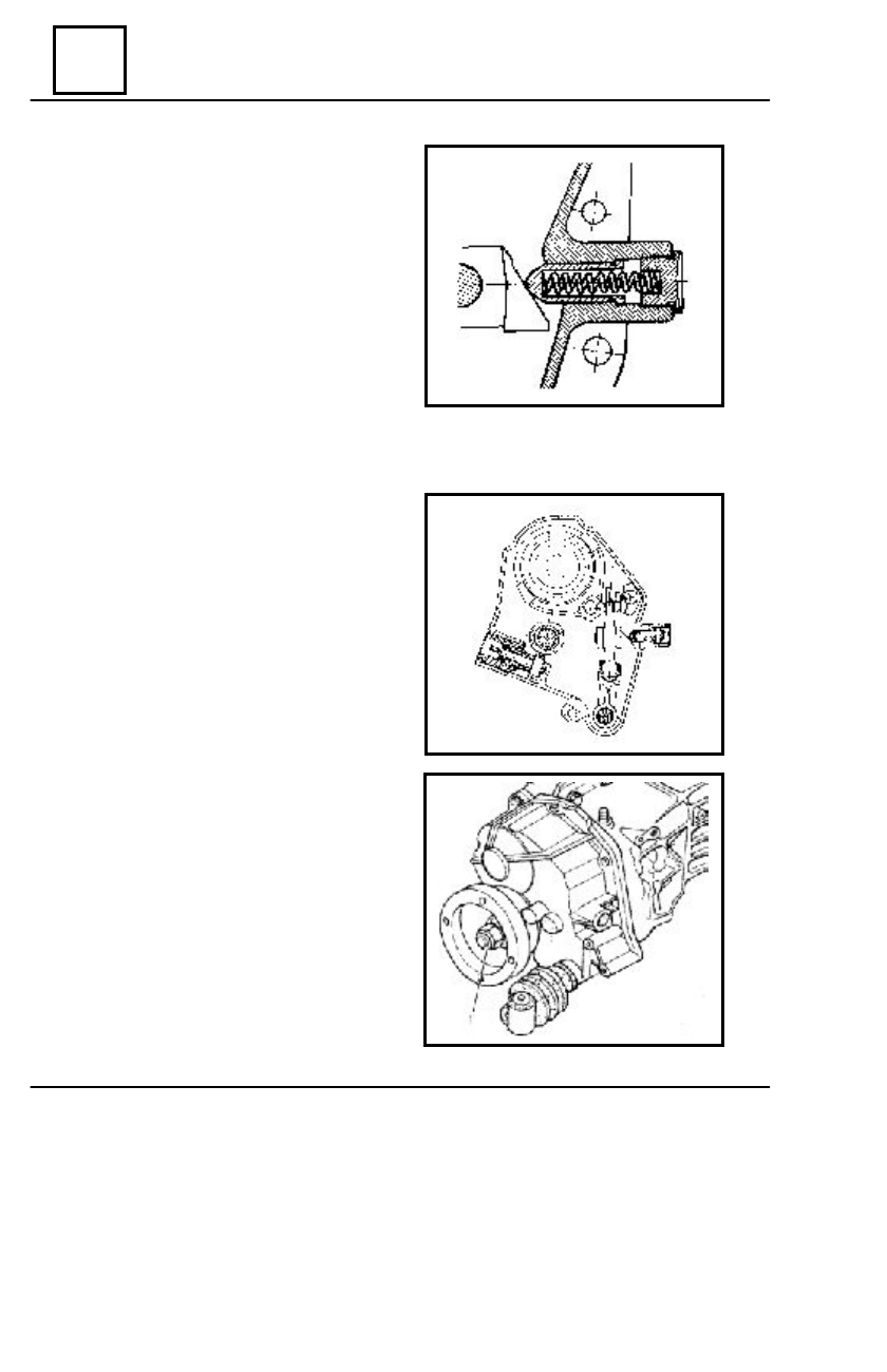
Mount :

 - the velocity step V pusher;
-  the spring;
-  the gasket;
-   the plug greased with LOCTITE 577

and tighten at the required couple (1,1-1,5daNm)

Bring the forks to the dead point.
Place the  back cap gasket lubricate with

oil.

Place the back cap; position the velocity  steps

selector in the forks shafts notches.

Tighten at the required moment

(1- 1,4daNm) the  back cap attachment screws.

For G.B. 50C and 51C:
Fill the contact surface between the annular

seal and the flange with grease UM 170 Li Ca
Pb 2M.

Mount the flange of propeller shaft

 transmission.

Place the washer and tighten at required

moment (10 - 12daNm) the flange attachment
nut (1).

REPAIR

BACK  CAP  RE MOUNTING

MANUAL GEARBOX

21

21 - 43

CLUTCH CASING  RE MOUNTING

Press in the clutch casing the guiding bushing of the pressure bearing (only if it has

previously been dismounted).

Mount the annular oil seal of the clutch shaft by means of the device   CV 488.

NOTE: Before mounting, the annular oil seal shall be immersed in  80W/90.

Apply a layer of sealing paste LOCTITE 518 on the assembling area of the clutch casing

REMOUNTING THE COUPLING MECHANISM 4X4 (G.B. 51 C)

Check by visual inspection the state of the

mechanism elements and replace
damaged parts with new ones.

Mount the pins housing (13) and the claw

(12).

Mount using a press, by means of a metallic

strap, the bearing on the differential hub (if this
was previously dismounted).

Mount the assembly hub - the tooth gear

sliding mechanism (10), together with coupling
shaft and fork (11).

Place the washer  rut (9).
Mount the safety ring (8) on the propeller shaft

pinion.

Mount the cover (7).

REPAIR

with mechanisms crankcase.

Mount the clutch casing by means the device

CV 488 for oil seal ring protection.

Tighten the attachment screws of the clutch

casing at the required  moment.

 M8 : 2 - 2,8 daNm
 M10 : 3,2 - 4 daNm
Mount the reverse lamp contact, after its

thread has been greased with LOCTITE 577
and tighten it at required moment
(2,5 daNm).


12


11


13


10


9


8


7

MANUAL GEARBOX

21

21 - 44

REPAIR

Replace the annular  oil seal from  the

differential cap,  as follows:

- grease the new annular oil seal with gear

oil 80W90;

- mount the new annular oil seal by slightly

tapping by means of the plastic hammer until it  came
into contact with the support shoulder from the
differential cap resulting in this case the dimension
of  6 + 0,5 mm.

Mount the differential cap assembly with a new

lubricated gasket.

Grease de contact surface between the  flange

and differential hub with sealing paste  LOCTITE
518

.

Necessary  quantity: 2 ml.
Mount the flange and deflector.
Tighten the screws at the required

 moment:

- differential cap      - 1,2 daNm;
- differential flange  - 2,4 daNm.

Mount the threaded  plug (4) for limiting the

stroke.

Mount the control lever (3) and secure with

safety ring  (2) (position the end of lever in the notch
of the control shaft.

Check the front transmission engagement and

disengagement.

Mount the vacuum capsule bracket on the

gearbox casing.

Mount the connecting bolt (1) between the

vacuum capsule shaft and the control lever and
secure with the attachment pin.

3

4

2

1

6

+/ -0,5

MANUAL GEARBOX

21

21 - 45

BACK CAP

D

ISMO UNTING

Lift the car on the elevator.
Drain the oil from the gearbox.
Disconnect:

 - the speedometer cable;
 - the velocity steps control.

Support the back part of the gearbox.
Unscrew the attachment nut  of the  exhaust

pipe from back cap cross bar gearbox.

Dismount the back crossbar of gearbox.
For G.B. 50C and 51C:

- dismount the cardan transmission from

the secondary shaft flange and tilt it over.

- dismount the secondary shaft  flange.

Engage the gear velocity step IV
Unscrew the back cap attachment screws.
Dismount the back cap

NOTE:

The velocity step V fork shaft shall not

be dismounted because the
 interlocking ball may fall; their
mounting implies dismounting the whole
gearbox.

R

EMOUNTING

Clean the contact surface of the gasket.
Place a new paper gasket after it was

lubricated with oil.

Place the back cap; position the velocity

steps selector in the forks shafts grooves.

Place the cap attachment screws and

tighten them at the required moment of
1,2daNm.

For  G.B. 50C and 51C:

- mount the driving flange of cardan

transmission and tighten the attachment nut at
the required couple (10 -12 daNm);

- engage the cardan transmission.

Mount the back support of the gearbox.
Connect :

           - the speedometer cable;
            - the velocity steps control.

Fill up the gearbox with oil   80W/90.

(on vehicle )


Content   ..  57  58  59  60   ..