Renault Scenic 3 Chassis. Manual - part 42


  Index      Renault     Renault Scenic 3 Chassis - Manual


Search            


Content   ..  40  41  42  43   ..


Renault Scenic 3 Chassis. Manual - part 42


37A

-

59

MECHANICAL COMPONENT CONTROLS

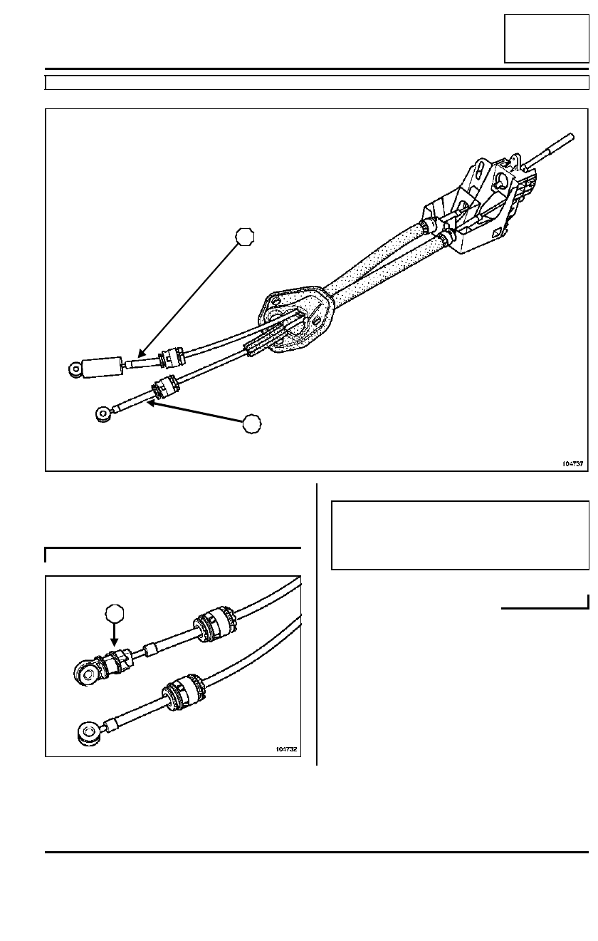
External gear control: Description

JH3 or JR5 or ND0

37A

104737

2

1

(1)

Selector cable.

(2)

Gear change cable.

ND0

104732

3

Note:

The external control of the ND0 gearbox has the
same features as those of JH / JR gearboxes except
for the adjustment system (3) on the selector cable.

37A

-

60

MECHANICAL COMPONENT CONTROLS

External gear control

JH3 or JR5 or ND0

37A

REMOVAL

Put the vehicle on a two-post lift.

Disconnect the battery starting with the negative ter-
minal.

Remove the engine covers.

Remove the scuttle grille ( Wiping - WashingSec-
tion).

Remove:

- both air filter access flap mounting bolts,(1)

- the air filter access panel,

- the plenum chamber partition mounting bolt (2).

Remove:

- the plenum chamber partition mounting bolts (3),

- the plenum chamber partition panel.

Tightening torques

m

control unit mounting
bolts

2.1 daNm

104343

1

2

104246

3

3

37A

-

61

MECHANICAL COMPONENT CONTROLS

External gear control

JH3 or JR5 or ND0

37A

Remove:

- the battery,

- the battery tray,

- the computer and its mounting.

- the air filter outlet duct.

Remove the two lever cables on the gearbox:

- at the two anchoring ball joints ,

- at the sleeve stops.

Remove:

- the gear lever knob by lifting it,

- the gear lever gaiter.

Remove the mounting screws for the central conso-
le.(4)

Unclip:

- the central console mounting brackets(5),

- the clip (6).

Remove the three control unit mounting nuts(9).

104241

WARNING

- If the anchoring clip is damaged it must be

replaced (see  Mechanical component con-
trols
Section).

- Do not touch the adjustment system on the ND

gearbox selector cables, as this would alter the
length of the cable and consequently the move-
ment of the gear lever.

104033

103582

4

6

5

9

9

37A

-

62

MECHANICAL COMPONENT CONTROLS

External gear control

JH3 or JR5 or ND0

37A

Remove the three bulkhead seal mounting bolts
(10).

Remove the engine undertray.

Disconnect:

- the exhaust pipe from the manifold,

- the centre bracket.

Move the exhaust pipe to the side (see  Turbochar-
ging
Section).

Remove the heat shield mountings.

Move the heat shield towards the rear of the vehicle
to gain access to the gearbox selector cable routing
(11).

Remove the gear lever unit.

REFITTING

To refit, proceed in the reverse order to removal.

Refit the heat shield correctly.

Tighten to torque the control unit mounting bolts
(2.1 daNm)
.

ADJUSTING THE GEARBOX CABLES

Refit the cables in their respective sleeve stops.

Fit the cables into their respective ball joints.

Check that all the gears engage correctly before
starting the engine.

I -  WITHOUT REPLACING A COMPONENT OR 
WITH A GEAR CHANGE CABLE:

II - WITH REPLACEMENT OF THE COMPLETE 
EXTERNAL CONTROL OR THE GEAR SELECTOR 
CABLE:

Refit the control unit.

104670

104734

10

10

11

JH3 or JR5

Note:

- the selector cable can be identified by a « B »

mark stamped on the sleeve stop,

- There is no cable adjustment system.

- The external control unit and the selector levers

on the gearbox must be in the neutral position
when the cables are attached to the levers.

ND0

Note:

- There is no cable adjustment system.

- The external control unit and the control levers

on the gearbox must be in « neutral » when the
cables are attached to the levers.


Content   ..  40  41  42  43   ..