Peugeot 405 Haynes (petrol). Manual - part 35


  Index      Manuals     Peugeot 405 Haynes (petrol) 1.4 (1360 cc), 1.6 (1580 cc), 1.8 (1761 cc), 1.9 (1905 cc) and 2.0 (1998 cc). Repair Manual


Search            


Content   ..  33  34  35  36   ..


Peugeot 405 Haynes (petrol). Manual - part 35


12•54

Wiring diagrams

B

A

C

D

E

F

G

H

J

K

L

M

2

1

3

4

5

6

7

8

B

A

C

D

E

F

G

H

J

K

L

M

2

1

3

4

5

6

7

8

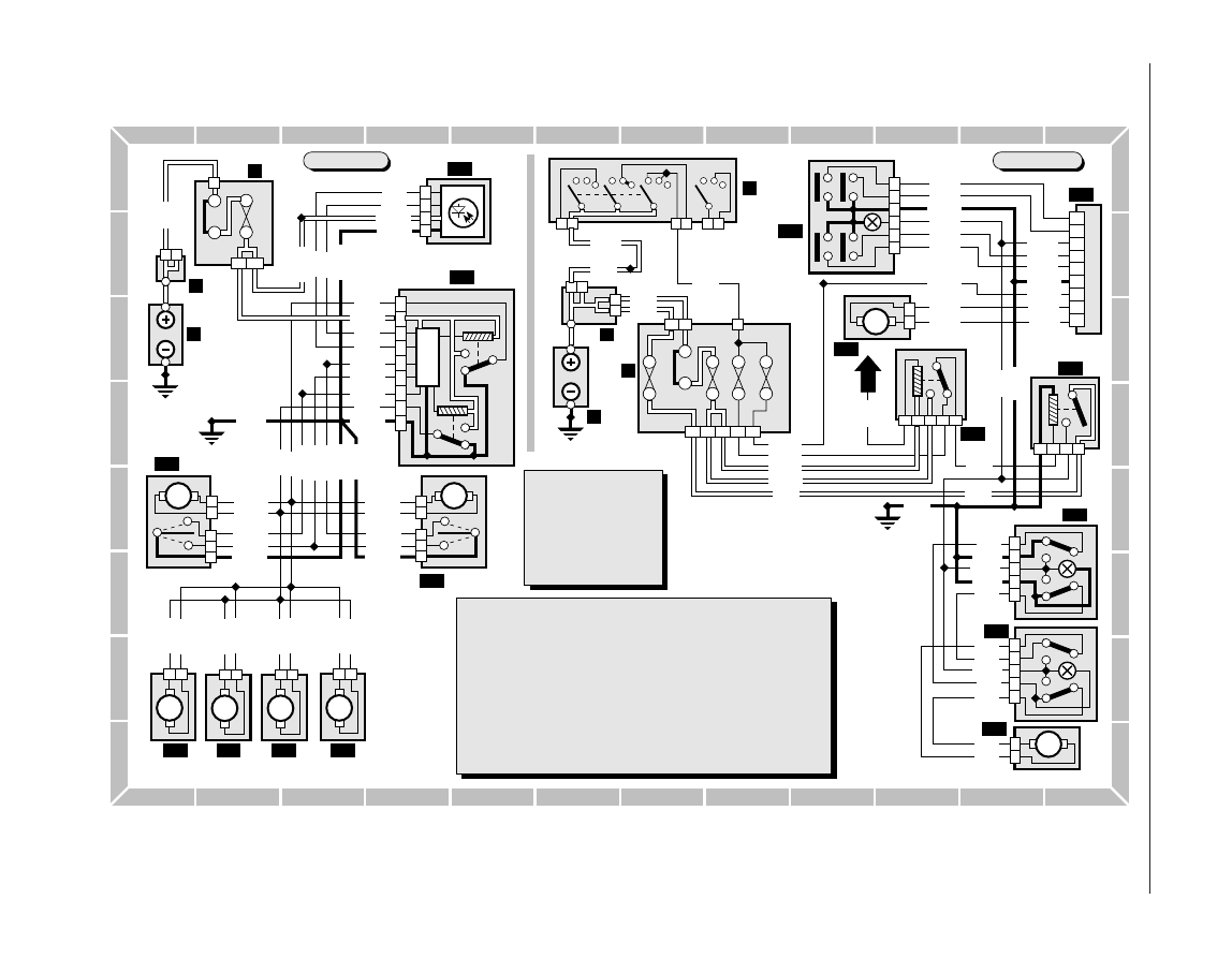
Diagram 13 : Central locking and electric windows - later models

H29192

T.M.MARKE

1

Battery

2

Battery +ve control unit

3

Fusebox

4

Ignition switch

122 Door locking control unit
123 Infra red receiver
124 RH front door lock
125 LH front door lock
126 RH rear door lock
127 LH rear door lock
128 Tailgate lock motor

129 Fuel filler lock motor
130 Electric window and sunroof relay
131 Electric window and sunroof

reconnection relay

132 Instantaneous electric window unit
133 RH front window motor
134 RH door switch for RH window
135 RH door switch for LH window
136 LH door switch for LH window
137 LH front window motor

Key to items

2

1

3

1

7A 7B

VE

F15

NR

F8

1

E000

2

NR

BB1

2

1

7

8

NR

1 2

MR

M

MR

M

1

2

3

2

1

BA

4

1

6

9

MR

7

5

8

3

2

1 2

BA

M

1 2

MR

M

MR

M

1

2

3

2

1

BA

B153

B152

B151

627

628

628

627

E020

MPB

M623

M623

M623

M620

6251

6252

M620

6251

6252

6251

6231

M620

6231

6231

6252
6232

M620

628

627

621

6212

621

6211

1 2

BA

M

6213

6216

6215

6213

6202

6201

620

620

6203

6206

6205

6203

123

122

125

124

127

128

129

126

Central locking

2

1

1

E000

2

1

GR

NR

1

2

2

1

4

2

BB5

BB10

AA2

GR

3

F29

NR

F8

1

MR

F28

MR

NR

2

1

BB1

F15

2

1

BB2

F30

3A

6A

7B

2A 4B

NR

5

2

4

1

3

NR

5

2

3

1

B155
B156

A282

12/M5

305

601

B29

B29

M

6050

6040

6051

6052

6042

6041

2

1

GR

4A

1A

3B

2A

2B

4B

5A

5B

1B

RG

4

5

2

6

3

7

BE

A302

A301

6001

600

M600

M603

6005
6052
6051

A301
6040

6050

M602

E020

MPB

4

3

5

2

1

MR

M

1

2

GR

608

607

606

6002

6003

M606

M607

4

3

5

2

1

MR

609

608

609

606

607

Electric windows

BA White
GR Grey
MR Brown
BE Blue
RS Pink
VE Green

Connector colours

BG Beige
JN Yellow
RG Red
OR Orange
VI

Mauve

NR Black

130

131

132

133

134

135

136

137

Dimensions and Weights  . . . . . . . . . . . . . . . . . . REF•1

Conversion Factors  . . . . . . . . . . . . . . . . . . . . . . . REF•2

Buying Spare Parts  . . . . . . . . . . . . . . . . . . . . . . .REF•3

Vehicle Identification  . . . . . . . . . . . . . . . . . . . . . . REF•3

General Repair Procedures  . . . . . . . . . . . . . . . . . REF•4

Jacking and Vehicle Support  . . . . . . . . . . . . . . . REF•5

Radio/cassette unit Anti-theft System  . . . . . . . . REF•5

Tools and Working Facilities  . . . . . . . . . . . . . . . . REF•6

MOT Test Checks  . . . . . . . . . . . . . . . . . . . . . . . .REF•8

Fault Finding  . . . . . . . . . . . . . . . . . . . . . . . . . . . REF•12

Glossary of Technical Terms . . . . . . . . . . . . . . . REF•20

Index  . . . . . . . . . . . . . . . . . . . . . . . . . . . . . . . . . REF•25

Reference

REF•1

REF

Dimensions and weights

Note: All figures are approximate, and may vary according to model.
Refer to manufacturer’s data for exact figures.

Dimensions

Overall length:

Saloon  . . . . . . . . . . . . . . . . . . . . . . . . . . . . . . . . . . . . . . . . .4408 mm
Estate  . . . . . . . . . . . . . . . . . . . . . . . . . . . . . . . . . . . . . . . . .4398 mm

Overall width:

Saloon  . . . . . . . . . . . . . . . . . . . . . . . . . . . . . . . . . . . . . . . . .1714 mm
Estate  . . . . . . . . . . . . . . . . . . . . . . . . . . . . . . . . . . . . . . . . .1707 mm

Overall height (unladen):

Saloon  . . . . . . . . . . . . . . . . . . . . . . . . . . . . . . . . . . . . . . . . .1406 mm
Estate  . . . . . . . . . . . . . . . . . . . . . . . . . . . . . . . . . . . . . . . . .1445 mm

Wheelbase:

All models  . . . . . . . . . . . . . . . . . . . . . . . . . . . . . . . . . . . . . .2669 mm

Weights

Kerb weight:

Saloon  . . . . . . . . . . . . . . . . . . . . . . . . . . . . . . . . . . .1030 to 1100 kg*
Estate  . . . . . . . . . . . . . . . . . . . . . . . . . . . . . . . . . . .1090 to 1160 kg*

Maximum gross vehicle weight:

Saloon  . . . . . . . . . . . . . . . . . . . . . . . . . . . . . . . . . . .1470 to 1580 kg*
Estate  . . . . . . . . . . . . . . . . . . . . . . . . . . . . . . . . . . .1590 to 1660 kg*

Maximum towing weight:

Unbraked trailer:

Saloon  . . . . . . . . . . . . . . . . . . . . . . . . . . . . . . . . . . .515 to 560 kg*
Estate . . . . . . . . . . . . . . . . . . . . . . . . . . . . . . . . . . . .540 to 580 kg*

Braked trailer:

Saloon  . . . . . . . . . . . . . . . . . . . . . . . . . . . . . . . . . .900 to 1200 kg*
Estate  . . . . . . . . . . . . . . . . . . . . . . . . . . . . . . . . . . . . . . . . .1200 kg

Maximum trailer nose weight . . . . . . . . . . . . . . . . . . . . . . . . . . . . .65 kg
*Depending on model and specification.

REF•2

Conversion Factors

Length (distance)

Inches (in)

25.4

= Millimetres (mm)

x 0.0394 = Inches (in)

Feet (ft)

0.305

= Metres (m)

x 3.281

= Feet (ft)

Miles

1.609

= Kilometres (km)

x 0.621

= Miles

Volume (capacity)

Cubic inches (cu in; in

3

)

x 16.387 = Cubic centimetres (cc; cm

3

)

x 0.061

= Cubic inches (cu in; in

3

)

Imperial pints (Imp pt)

x 0.568

= Litres (l)

x 1.76

= Imperial pints (Imp pt)

Imperial quarts (Imp qt)

x 1.137

= Litres (l)

x 0.88

= Imperial quarts (Imp qt)

Imperial quarts (Imp qt)

x 1.201

= US quarts (US qt)

x 0.833

= Imperial quarts (Imp qt)

US quarts (US qt)

x 0.946

= Litres (l)

x 1.057

= US quarts (US qt)

Imperial gallons (Imp gal)

x 4.546

= Litres (l)

x 0.22

= Imperial gallons (Imp gal)

Imperial gallons (Imp gal)

x 1.201

= US gallons (US gal)

x 0.833

= Imperial gallons (Imp gal)

US gallons (US gal)

x  3.785

= Litres (l)

x  0.264

= US gallons (US gal)

Mass (weight)

Ounces (oz)

x 28.35

= Grams (g)

x 0.035

= Ounces (oz)

Pounds (lb)

x 0.454

= Kilograms (kg)

x 2.205

= Pounds (lb)

Force

Ounces-force (ozf; oz)

x 0.278

= Newtons (N)

x 3.6

= Ounces-force (ozf; oz)

Pounds-force (lbf; lb)

x 4.448

= Newtons (N)

x 0.225

= Pounds-force (lbf; lb)

Newtons (N)

x 0.1

= Kilograms-force (kgf; kg)

x 9.81

= Newtons (N)

Pressure

Pounds-force per square inch

x 0.070

= Kilograms-force per square

x 14.223 = Pounds-force per square inch

(psi; lbf/in

2

; lb/in

2

)

centimetre (kgf/cm

2

; kg/cm

2

)

(psi; lbf/in

2

; lb/in

2

)

Pounds-force per square inch

x 0.068

= Atmospheres (atm)

x 14.696 = Pounds-force per square inch

(psi; lbf/in

2

; lb/in

2

)

(psi; lbf/in

2

; lb/in

2

)

Pounds-force per square inch

x 0.069

= Bars

x 14.5

= Pounds-force per square inch

(psi; lbf/in

2

; lb/in

2

)

(psi; lbf/in

2

; lb/in

2

)

Pounds-force per square inch

x 6.895

= Kilopascals (kPa)

x 0.145

= Pounds-force per square inch

(psi; lbf/in

2

; lb/in

2

)

(psi; lbf/in

2

; lb/in

2

)

Kilopascals (kPa)

x 0.01

= Kilograms-force per square

x 98.1

= Kilopascals (kPa)

centimetre (kgf/cm

2

; kg/cm

2

)

Millibar (mbar)

x 100

= Pascals (Pa)

x 0.01

= Millibar (mbar)

Millibar (mbar)

x 0.0145 = Pounds-force per square inch

x 68.947 = Millibar (mbar)

(psi; lbf/in

2

; lb/in

2

)

Millibar (mbar)

x 0.75

= Millimetres of mercury (mmHg)

x 1.333

= Millibar (mbar)

Millibar (mbar)

x 0.401

= Inches of water (inH

2

O)

x 2.491

= Millibar (mbar)

Millimetres of mercury (mmHg)

x 0.535

= Inches of water (inH

2

O)

x 1.868

= Millimetres of mercury (mmHg)

Inches of water (inH

2

O)

x 0.036

= Pounds-force per square inch

x 27.68

= Inches of water (inH

2

O)

(psi; lbf/in

2

; lb/in

2

)

Torque (moment of force)

Pounds-force inches (lbf in; lb in)

x 1.152

= Kilograms-force centimetre 

x 0.868

= Pounds-force inches (lbf in; lb in)

(kgf cm; kg cm)

Pounds-force inches (lbf in; lb in)

x 0.113

= Newton metres (Nm)

x 8.85

= Pounds-force inches (lbf in; lb in)

Pounds-force inches (lbf in; lb in)

x 0.083

= Pounds-force feet (lbf ft; lb ft)

x 12

= Pounds-force inches (lbf in; lb in)

Pounds-force feet (lbf ft; lb ft)

x 0.138

= Kilograms-force metres (kgf m; kg m)

x 7.233

= Pounds-force feet (lbf ft; lb ft)

Pounds-force feet (lbf ft; lb ft)

x 1.356

= Newton metres (Nm)

x 0.738

= Pounds-force feet (lbf ft; lb ft)

Newton metres (Nm)

x 0.102

= Kilograms-force metres (kgf m; kg m)

x 9.804

= Newton metres (Nm)

Power

Horsepower (hp)

x 745.7

= Watts (W)

x 0.0013 = Horsepower (hp)

Velocity (speed)

Miles per hour (miles/hr; mph)

x 1.609

= Kilometres per hour (km/hr; kph)

x 0.621

= Miles per hour (miles/hr; mph)

Fuel consumption*

Miles per gallon (mpg)

x 0.354

= Kilometres per litre (km/l)

x 2.825

= Miles per gallon (mpg)

* It is common practice to convert from miles per gallon (mpg) to litres/100 kilometres (l/100km), where mpg x l/100 km = 282 

Temperature

Degrees Fahrenheit = (°C x 1.8) + 32

Degrees Celsius (Degrees Centigrade; °C) = (°F - 32) x 0.56

Spare parts are available from many sources,

including maker’s appointed garages, accessory
shops, and motor factors. To be sure of
obtaining the correct parts, it may sometimes be
necessary to quote the vehicle identification
number. If possible, it can also be useful to take
the old parts along for positive identification.
Items such as starter motors and alternators
may be available under a service exchange
scheme - any parts returned should be clean.

Our advice regarding spare part sources is

as follows.

Officially-appointed garages

This is the best source of parts which are

peculiar to your car, and are not otherwise
generally available (eg badges, interior trim,
certain body panels, etc). It is also the only
place at which you should buy parts if the
vehicle is still under warranty. 

Accessory shops

These are good places to buy materials and

components needed for the maintenance of
your car (oil, air and fuel filters, spark plugs,
light bulbs, drivebelts, oils and greases, brake
pads, touch-up paint, etc). Parts like this sold
by a reputable shop are of the same standard
as those used by the car manufacturer.

Motor factors

Good factors will stock all the more

important components which wear out
comparatively quickly and can sometimes
supply individual components needed for the
overhaul of a larger assembly. They may also
handle work such as cylinder block reboring,
crankshaft regrinding and balancing, etc.

Tyre and exhaust specialists

These outlets may be independent or

members of a local or national chain. They
frequently offer competitive prices when
compared with a main dealer or local garage,
but it will pay to obtain several quotes before
making a decision. Also ask what ‘extras’ may
be added  to the quote - for instance, fitting a
new valve and balancing the wheel are both
often charged on top of the price of a new
tyre.

Other sources

Beware of parts or materials obtained from

market stalls, car boot sales or similar outlets.
Such items are not invariably sub-standard,
but there is little chance of compensation if
they do prove unsatisfactory. In the case of
safety-critical components such as brake
pads there is the risk not only of financial loss
but also of an accident causing injury or
death.

Buying Spare Parts

REF•3

REF

Vehicle identification numbers

Modifications are a continuing and

unpublicised process in vehicle manufacture,
quite apart from major model changes. Spare
parts lists are compiled upon a numerical
basis, the individual vehicle identification
numbers being essential to correct identifi-
cation of the component concerned.

When ordering spare parts, always give as

much information as possible. Quote the car
model, year of manufacture, body and engine
numbers, as appropriate.

The  Vehicle Identification Number (VIN)

plate is riveted to the top of the front cross
panel in the engine compartment. It is also
stamped into the right-hand side of the engine
bulkhead.

The Engine number is situated on the front

of the cylinder block, just below the cylinder
head. On TU engines it is near the left-hand
end of the engine, on XU10 engines it is mid-
way, and on XU5, XU7 and XU9 engines it is
on the right-hand end. Note: The first part of
the engine number gives the engine code - 
eg, “XU5”.

The Vehicle paint code is stamped into the

left-hand inner wing panel.

Other identification numbers or codes are

stamped on major items such as the gearbox,
final drive housing, distributor etc.

Location of Vehicle Identification Plates

1  Vehicle identification plate
2  Vehicle identification number
3  Vehicle paint colour code

Whenever servicing, repair or overhaul work

is carried out on the car or its components, it
is necessary to observe the following
procedures and instructions. This will assist in
carrying out the operation efficiently and to a
professional standard of workmanship.

Joint mating faces and gaskets

When separating components at their

mating faces, never insert screwdrivers or
similar implements into the joint between the
faces in order to prise them apart. This can
cause severe damage which results in oil
leaks, coolant leaks, etc upon reassembly.
Separation is usually achieved by tapping
along the joint with a soft-faced hammer in
order to break the seal. However, note that
this method may not be suitable where
dowels are used for component location.

Where a gasket is used between the mating

faces of two components, ensure that it is
renewed on reassembly, and fit it dry unless
otherwise stated in the repair procedure. Make
sure that the mating faces are clean and dry,
with all traces of old gasket removed. When
cleaning a joint face, use a tool which is not
likely to score or damage the face, and remove
any burrs or nicks with an oilstone or fine file.

Make sure that tapped holes are cleaned

with a pipe cleaner, and keep them free of
jointing compound, if this is being used,
unless specifically instructed otherwise.

Ensure that all orifices, channels or pipes

are clear, and blow through them, preferably
using compressed air.

Oil seals

Oil seals can be removed by levering them

out with a wide flat-bladed screwdriver or
similar tool. Alternatively, a number of self-
tapping screws may be screwed into the seal,
and these used as a purchase for pliers or
similar in order to pull the seal free.

Whenever an oil seal is removed from its

working location, either individually or as part
of an assembly, it should be renewed.

The very fine sealing lip of the seal is easily

damaged, and will not seal if the surface it
contacts is not completely clean and free from
scratches, nicks or grooves. If the original
sealing surface of the component cannot be
restored, and the manufacturer has not made
provision for slight relocation of the seal
relative to the sealing surface, the component
should be renewed.

Protect the lips of the seal from any surface

which may damage them in the course of
fitting. Use tape or a conical sleeve where
possible. Lubricate the seal lips with oil before
fitting and, on dual-lipped seals, fill the space
between the lips with grease.

Unless otherwise stated, oil seals must be

fitted with their sealing lips toward the
lubricant to be sealed.

Use a tubular drift or block of wood of the

appropriate size to install the seal and, if the
seal housing is shouldered, drive the seal
down to the shoulder. If the seal housing is

unshouldered, the seal should be fitted with
its face flush with the housing top face (unless
otherwise instructed).

Screw threads and fastenings

Seized nuts, bolts and screws are quite a

common occurrence where corrosion has set
in, and the use of penetrating oil or releasing
fluid will often overcome this problem if the
offending item is soaked for a while before
attempting to release it. The use of an impact
driver may also provide a means of releasing
such stubborn fastening devices, when used
in conjunction with the appropriate
screwdriver bit or socket. If none of these
methods works, it may be necessary to resort
to the careful application of heat, or the use of
a hacksaw or nut splitter device.

Studs are usually removed by locking two

nuts together on the threaded part, and then
using a spanner on the lower nut to unscrew
the stud. Studs or bolts which have broken off
below the surface of the component in which
they are mounted can sometimes be removed
using a stud extractor. Always ensure that a
blind tapped hole is completely free from oil,
grease, water or other fluid before installing
the bolt or stud. Failure to do this could cause
the housing to crack due to the hydraulic
action of the bolt or stud as it is screwed in.

When tightening a castellated nut to accept

a split pin, tighten the nut to the specified
torque, where applicable, and then tighten
further to the next split pin hole. Never
slacken the nut to align the split pin hole,
unless stated in the repair procedure.

When checking or retightening a nut or bolt

to a specified torque setting, slacken the nut
or bolt by a quarter of a turn, and then
retighten to the specified setting. However,
this should not be attempted where angular
tightening has been used.

For some screw fastenings, notably

cylinder head bolts or nuts, torque wrench
settings are no longer specified for the latter
stages of tightening, “angle-tightening” being
called up instead. Typically, a fairly low torque
wrench setting will be applied to the
bolts/nuts in the correct sequence, followed
by one or more stages of tightening through
specified angles.

Locknuts, locktabs and washers

Any fastening which will rotate against a

component or housing during tightening
should always have a washer between it and
the relevant component or housing.

Spring or split washers should always be

renewed when they are used to lock a critical
component such as a big-end bearing
retaining bolt or nut. Locktabs which are
folded over to retain a nut or bolt should
always be renewed.

Self-locking nuts can be re-used in non-

critical areas, providing resistance can be felt
when the locking portion passes over the bolt
or stud thread. However, it should be noted
that self-locking stiffnuts tend to lose their

effectiveness after long periods of use, and
should be renewed as a matter of course.

Split pins must always be replaced with

new ones of the correct size for the hole.

When thread-locking compound is found

on the threads of a fastener which is to be re-
used, it should be cleaned off with a wire
brush and solvent, and fresh compound
applied on reassembly.

Special tools

Some repair procedures in this manual

entail the use of special tools such as a press,
two or three-legged pullers, spring
compressors, etc. Wherever possible, suitable
readily-available alternatives to the
manufacturer’s special tools are described,
and are shown in use. In some instances,
where no alternative is possible, it has been
necessary to resort to the use of a
manufacturer’s tool, and this has been done
for reasons of safety as well as the efficient
completion of the repair operation. Unless you
are highly-skilled and have a thorough
understanding of the procedures described,
never attempt to bypass the use of any
special tool when the procedure described
specifies its use. Not only is there a very great
risk of personal injury, but expensive damage
could be caused to the components involved.

Environmental considerations

When disposing of used engine oil, brake

fluid, antifreeze, etc, give due consideration to
any detrimental environmental effects. Do not,
for instance, pour any of the above liquids
down drains into the general sewage system,
or onto the ground to soak away. Many local
council refuse tips provide a facility for waste
oil disposal, as do some garages. If none of
these facilities are available, consult your local
Environmental Health Department, or the
National Rivers Authority, for further advice.

With the universal tightening-up of

legislation regarding the emission of environ-
mentally-harmful substances from motor
vehicles, most current vehicles have
tamperproof devices fitted to the main
adjustment points of the fuel system. These
devices are primarily designed to prevent
unqualified persons from adjusting the fuel/air
mixture, with the chance of a consequent
increase in toxic emissions. If such devices
are encountered during servicing or overhaul,
they should, wherever possible, be renewed
or refitted in accordance with the vehicle
manufacturer’s requirements or current
legislation.

REF•4

General Repair Procedures

Note: It is
antisocial and
illegal to dump oil
down the drain.
To find the
location of your
local oil recycling
bank, call this
number free.

The jack supplied with the vehicle tool kit

should only be used for changing the
roadwheels - see “Wheel changing” at the
front of this manual. When carrying out any
other kind of work, raise the vehicle using a
hydraulic (or “trolley”) jack, and always
supplement the jack with axle stands
positioned under the vehicle jacking points.

When using a hydraulic jack or axle stands,

always position the jack head or axle stand
head under, or adjacent to one of the relevant
wheel changing jacking points  (see
illustration)
.

To raise the front of the vehicle, position the

jack with an interposed block of wood
underneath the centre of the front subframe.
Alternatively, the vehicle can be jacked under
the front crossmember, but a block of wood
100 x 100 x 780 mm will be required between
the jack and the crossmember. Do not jack
the vehicle under the sump, or any of the
steering or suspension components.

The procedure for raising the rear of the

vehicle is as described for the front, but place
the jack under either the rear axle tube, for
which a shaped block of wood approximately
100 mm long will be required, or under the
rear panel using a 150 x 150 x 1200 mm block
of wood. Do not attempt to raise the vehicle
with the jack positioned under the spare
wheel, as the vehicle floor will almost certainly
be damaged.

The jack supplied with the vehicle located

in the jacking points in the ridges on the
underside of the sills. Ensure that the jack
head is correctly engaged before attempting
to raise the vehicle.

Never work under, around, or near a raised

vehicle, unless it is adequately supported in at
least two places.

Jacking and Vehicle Support

REF•5

REF

Radio/cassette unit Anti-theft System - Precaution

The radio/cassette unit fitted to later

models as standard equipment by Peugeot is
equipped with a built-in security code, to
deter thieves. If the power source to the unit is
cut, the anti-theft system will activate. Even if
the power source is immediately reconnected,
the radio/cassette unit will not function until
the correct security code has been entered.
Therefore if you do not know the correct
security code for the unit, do not disconnect

the battery negative lead, or remove the
radio/cassette unit from the vehicle.

To enter the security code, press the

“on/off” button; the unit display will show
“CODE”.The security code can then be
entered using the buttons 1 to 6 on the unit.
The unit will be activated automatically if the
correct code is entered.

If the incorrect code is entered, the unit will

lock, and the word “SECURITY” will be

displayed for 2 minutes. After 2 minutes, it will
be possible to enter a code again. If 3 wrong
codes are entered, the unit will lock for 2 hours.
To clear the locking function, leave the unit and
the ignition switched on during this period.

If the security code is lost or forgotten, seek

the advice of your Peugeot dealer. On
presentation of proof of ownership, a Peugeot
dealer will be able to provide you with a new
security code.

Vehicle jacking points

Introduction

A selection of good tools is a fundamental

requirement for anyone contemplating the
maintenance and repair of a motor vehicle.
For the owner who does not possess any,
their purchase will prove a considerable
expense, offsetting some of the savings made
by doing-it-yourself. However, provided that
the tools purchased meet the relevant national
safety standards and are of good quality, they
will last for many years and prove an
extremely worthwhile investment.

To help the average owner to decide which

tools are needed to carry out the various tasks
detailed in this manual, we have compiled
three lists of tools under the following
headings: Maintenance and minor repair,
Repair and overhaul
, and Special. Newcomers
to practical mechanics should start off with
the Maintenance and minor repair tool kit, and
confine themselves to the simpler jobs around
the vehicle. Then, as confidence and
experience grow, more difficult tasks can be
undertaken, with extra tools being purchased
as, and when, they are needed. In this way, a
Maintenance and minor repair tool kit can be
built up into a Repair and overhaul tool kit over
a considerable period of time, without any
major cash outlays. The experienced do-it-
yourselfer will have a tool kit good enough for
most repair and overhaul procedures, and will
add tools from the Special category when it is
felt that the expense is justified by the amount
of use to which these tools will be put.

Maintenance 
and minor repair tool kit

The tools given in this list should be

considered as a minimum requirement if
routine maintenance, servicing and minor
repair operations are to be undertaken. We
recommend the purchase of combination
spanners (ring one end, open-ended the
other); although more expensive than open-
ended ones, they do give the advantages of
both types of spanner.
Combination spanners:

Metric - 8 to 19 mm inclusive

Adjustable spanner - 35 mm jaw (approx.)

Spark plug spanner (with rubber insert) - 

petrol models

Spark plug gap adjustment tool - petrol 

models

Set of feeler gauges

Brake bleed nipple spanner

Screwdrivers:

Flat blade - 100 mm long x 6 mm dia
Cross blade - 100 mm long x 6 mm dia

Combination pliers

Hacksaw (junior)

Tyre pump

Tyre pressure gauge

Oil can

Oil filter removal tool

Fine emery cloth

Wire brush (small)

Funnel (medium size)

Repair and overhaul tool kit

These tools are virtually essential for

anyone undertaking any major repairs to a
motor vehicle, and are additional to those
given in the Maintenance and minor repair list.
Included in this list is a comprehensive set of
sockets. Although these are expensive, they
will be found invaluable as they are so
versatile - particularly if various drives are
included in the set. We recommend the half-
inch square-drive type, as this can be used
with most proprietary torque wrenches. 

The tools in this list will sometimes need to

be supplemented by tools from the Special list:
Sockets (or box spanners) to cover range in

previous list (including Torx sockets)

Reversible ratchet drive (for use with 

sockets)

Extension piece, 250 mm (for use with 

sockets)

Universal joint (for use with sockets)

Torque wrench (for use with sockets)

Self-locking grips

Ball pein hammer

Soft-faced mallet (plastic/aluminium or 

rubber)

Screwdrivers:

Flat blade - long & sturdy, short (chubby), 
and narrow (electrician’s) types
Cross blade – Long & sturdy, and short 
(chubby) types

Pliers:

Long-nosed
Side cutters (electrician’s)
Circlip (internal and external)

Cold chisel - 25 mm

Scriber

Scraper

Centre-punch

Pin punch

Hacksaw

Brake hose clamp

Brake/clutch bleeding kit

Selection of twist drills

Steel rule/straight-edge

Allen keys (inc. splined/Torx type)

Selection of files

Wire brush

Axle stands

Jack (strong trolley or hydraulic type)

Light with extension lead

REF•6

Tools and Working Facilities

Sockets and reversible ratchet drive

Clutch plate alignment set

Piston ring compressor

Spline bit set

Valve spring compressor

Special tools

The tools in this list are those which are not

used regularly, are expensive to buy, or which
need to be used in accordance with their
manufacturers’ instructions. Unless relatively
difficult mechanical jobs are undertaken
frequently, it will not be economic to buy
many of these tools. Where this is the case,
you could consider clubbing together with
friends (or joining a motorists’ club) to make a
joint purchase, or borrowing the tools against
a deposit from a local garage or tool hire
specialist. It is worth noting that many of the
larger DIY superstores now carry a large
range of special tools for hire at modest rates.

The following list contains only those tools

and instruments freely available to the public,
and not those special tools produced by the
vehicle manufacturer specifically for its dealer
network. You will find occasional references
to these manufacturers’ special tools in the
text of this manual. Generally, an alternative
method of doing the job without the vehicle
manufacturers’ special tool is given. However,
sometimes there is no alternative to using
them. Where this is the case and the relevant
tool cannot be bought or borrowed, you will
have to entrust the work to a dealer.
Valve spring compressor

Valve grinding tool

Piston ring compressor

Piston ring removal/installation tool

Cylinder bore hone

Balljoint separator

Coil spring compressors (where applicable)

Two/three-legged hub and bearing puller

Impact screwdriver

Micrometer and/or vernier calipers

Dial gauge

Stroboscopic timing light

Dwell angle meter/tachometer

Universal electrical multi-meter

Cylinder compression gauge

Hand-operated vacuum pump and gauge

Clutch plate alignment set

Brake shoe steady spring cup removal tool

Bush and bearing removal/installation set

Stud extractors

Tap and die set

Lifting tackle

Trolley jack

Buying tools

Reputable motor accessory shops and

superstores often offer excellent quality tools
at discount prices, so it pays to shop around.

Remember, you don’t have to buy the most

expensive items on the shelf, but it is always
advisable to steer clear of the very cheap
tools. Beware of ‘bargains’ offered on market
stalls or at car boot sales. There are plenty of
good tools around at reasonable prices, but
always aim to purchase items which meet the
relevant national safety standards. If in doubt,
ask the proprietor or manager of the shop for
advice before making a purchase.

Care and maintenance of tools

Having purchased a reasonable tool kit, it is

necessary to keep the tools in a clean and
serviceable condition. After use, always wipe
off any dirt, grease and metal particles using a
clean, dry cloth, before putting the tools away.
Never leave them lying around after they have
been used. A simple tool rack on the garage
or workshop wall for items such as
screwdrivers and pliers is a good idea. Store
all normal spanners and sockets in a metal
box. Any measuring instruments, gauges,
meters, etc, must be carefully stored where
they cannot be damaged or become rusty.

Take a little care when tools are used.

Hammer heads inevitably become marked,
and screwdrivers lose the keen edge on their
blades from time to time. A little timely
attention with emery cloth or a file will soon
restore items like this to a good finish.

Working facilities

Not to be forgotten when discussing tools

is the workshop itself. If anything more than
routine maintenance is to be carried out, a
suitable working area becomes essential.

It is appreciated that many an owner-

mechanic is forced by circumstances to
remove an engine or similar item without the
benefit of a garage or workshop. Having done
this, any repairs should always be done under
the cover of a roof.

Wherever possible, any dismantling should

be done on a clean, flat workbench or table at
a suitable working height.

Any workbench needs a vice; one with a jaw

opening of 100 mm is suitable for most jobs.
As mentioned previously, some clean dry
storage space is also required for tools, as well
as for any lubricants, cleaning fluids, touch-up
paints etc, which become necessary.

Another item which may be required, and

which has a much more general usage, is an
electric drill with a chuck capacity of at least 8
mm. This, together with a good range of twist
drills, is virtually essential for fitting
accessories.

Last, but not least, always keep a supply of

old newspapers and clean, lint-free rags
available, and try to keep any working area as
clean as possible.

Tools and Working Facilities

REF•7

REF

Stroboscopic timing light 

Stud extractor set

Compression tester

Dial test indicator (“dial gauge”)

Micrometer set


Content   ..  33  34  35  36   ..