Peugeot 405 Haynes (petrol). Manual - part 26


  Index      Manuals     Peugeot 405 Haynes (petrol) 1.4 (1360 cc), 1.6 (1580 cc), 1.8 (1761 cc), 1.9 (1905 cc) and 2.0 (1998 cc). Repair Manual


Search            


Content   ..  24  25  26  27   ..


Peugeot 405 Haynes (petrol). Manual - part 2
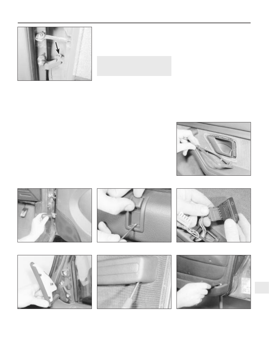
6


Ensure that the door is adequately
supported, then unscrew the pivot pins from
the hinges (see illustration).
Lift the door from the vehicle.

Refitting

Refitting is a reversal of removal, noting that
the hinge pins fit with their heads towards
each other, ie, the upper pin fits from below
the hinge, and the lower pin fits from above
the hinge.
On completion, check the fit of the door
with the surrounding body panels. On early
models, the fit of the doors can be adjusted as
described in paragraph 11.
10 If adjustment of the door lock is required,
this can be achieved by altering the position
of the lock striker within the elongated bolt
holes in the body pillar.

Adjustment - early models only

11 The fit of the door can be adjusted using

shims fitted between the hinge and the door.
To add or remove shims, loosen the bolts
securing the hinge to the door (the door inner
trim panel must be removed for access to the
bolts - see Section 13), then fit or remove
shims as necessary.

13 Door inner trim panel -

removal and refitting

3

Removal

If the trim is being in removed in order to
remove the window glass, lower the window
to approximately the two-thirds open position.
Carefully prise the surround from the door
interior handle (see illustration).
Remove the loudspeaker cover panel,
either by depressing the securing clip at the
lower edge of the panel, or by removing the
three securing screws from the edge of the
panel, as applicable (see illustration).
Unscrew the securing screws, withdraw the
loudspeaker, and disconnect the wiring.
Lift up the inner door lock operating button
then, using a small screwdriver, depress the
retaining tab, and slide off the button (see
illustration)
.
On models with manually-operated
windows, carefully pull the window regulator
handle from the door.
On models with electric windows,
disconnect the battery negative lead, then
prise the switches from the door, and
disconnect the wiring plugs (see illustration).

Prise the mirror trim plate from the front
corner of the door (see illustration). Where
applicable, loosen the clamp screw, and
release the mirror adjuster knob from the trim
plate.
Remove the securing screws and withdraw
the armrest (where applicable, prise the trim
plate from the armrest to expose the screws)
(see illustration).
10 On later models, prise the trim plate from
the rear of the door pocket, and unscrew the
rear trim panel securing screw (see illustration).
11 Where applicable, using a screwdriver,
release the trim panel securing clip located in
the loudspeaker aperture.
12 Working around the edge of the door,
release the remaining securing clips around
the edge of the trim panel, ideally using a
forked tool to avoid breaking the clips.
13 Lift the panel to release it from the top of
the door, then withdraw the panel. Where
applicable, disconnect the wiring plug from

Bodywork and fittings  11•7

13.3  Removing a loudspeaker cover panel

securing screw

13.8  Prise off the mirror trim plate

13.7  Removing an electric window switch

from the door

13.5  Depress the retaining tab and slide

off the lock operating button

13.2  Removing the door interior handle

surround

12.6  Door pivot pin (arrowed)

11

13.9  Remove the securing screws and

withdraw the armrest

13.10  Removing the rear door trim panel

securing screw - later model

the electric windows control unit, which is
located on a bracket attached to the rear of
the door trim panel.

Refitting

14 Refitting is a reversal of removal, bearing
in mind the following points.

a) Before refitting, check whether any of the

trim panel retaining clips were broken on
removal, and renew as necessary.

b) Ensure that the weatherstrip (with the

metal reinforcing strip) is in place on the
top of the trim panel before refitting, and
check that the weatherstrip engages
correctly with the weatherstrip on the
door as the trim panel is refitted.

c) To refit the inner door lock operating

button, first lock the door to ensure that
the link rod is in its lowest position.
Position the button locating tab in the
lower of its two holes, then firmly push

the button onto the rod until it clips into
position and the retaining tab appears in
the upper hole (see illustrations).

14 Door handle and lock

components - removal and
refitting

3

Interior door handle

Removal

Remove the door inner trim panel as
described in Section 13.
If necessary, peel the plastic sealing sheet
from around the handle assembly.
Slide the handle assembly towards the front
of the door, then pull the assembly from the
trim panel and disconnect the link rod (see
illustration)
. If necessary, release the link rod
from the clips on the door.

Refitting

Refitting is a reversal of removal, ensuring
the link rod is correctly reconnected. Where
applicable, fit a new sealing sheet if the sheet
was damaged during removal, and refit the
door trim panel with reference to Section 13.

Exterior door handle

Removal

Remove the door inner trim panel as
described in Section 13.
Peel back the plastic sealing sheet for
access to the handle securing nut.
Unscrew the handle securing nut then,
where applicable, manipulate the plastic shield
from the rear of the lock (see illustrations).
Withdraw the handle from outside the door,
and disconnect the lock operating rod from
the handle as it is removed (see illustration).

Refitting

Refitting is a reversal of removal, ensuring
that the link rod is correctly reconnected. Fit a
new sealing sheet if the sheet was damaged
during removal, and refit the door trim panel
with reference to Section 13.

Front door lock cylinder

10 The lock cylinder can be removed as
follows, without the need to remove the door
inner trim panel. If no facilities are available to
make up the tools, proceed to paragraph 11.

a) Make up two suitable tools, using a

medium-size self-tapping screw brazed to
a length of rod for each tool (see
illustration)
.

14.10a  Tool for removing 

door lock cylinder

All dimensions in mm

14.8  Withdrawing the exterior door handle

11•8 Bodywork and fittings

13.14a  Position the lock button locating

tab in the lower position

14.3  Unhooking the link rod from the

interior door handle

14.7c  . . . and withdraw the plastic shield -

later model

14.7b  Unscrew the securing nut . . .

14.7a  Exterior door handle securing nut

(arrowed) - early model

13.14b  Push the button onto the rod until

retaining tab appears in upper hole (arrowed)

b) Open the door, and prise the cover plates

from the rear edge of the door.

c) Insert the tools through the aperture in the

edge of the door, and screw the tools into
the lock securing clip as far as the ends of
the threads on the self-tapping screws.

d) Push the tools to release the securing

clip, and withdraw the lock cylinder from
outside the door (see illustration). Leave
the tools engaged with the clip.

e) Refit the lock, and use the tools to pull the

securing clip into position.

f) Ensure the clip is securely engaged with

the lock cylinder, then unscrew the tools
from the clip, and refit the cover plates.

Removal

11 Remove the door inner trim panel as
described in Section 13.
12 Peel back the plastic sealing sheet for
access to the lock cylinder securing clip.
13 Working inside the door, pull the clip from
the rear of the lock cylinder, then remove the
lock cylinder from outside the door (see
illustrations)
.

Refitting

14 Refitting is a reversal of removal, but
ensure that the lock cylinder clip is securely
refitted. Fit a new sealing sheet if the sheet
was damaged during removal, and refit the
door trim panel with reference to Section 13.

Door lock

Removal

15 Remove the door interior handle and the
exterior handle, as described previously in this
Section.

16 Working at the rear edge of the door,
unscrew the three lock securing screws (see
illustration)
.
17 Where applicable, disconnect the wiring
plug from the central locking motor on the
lock assembly.
18 Lower the lock assembly into the door,
and manipulate the lock operating rods until
the assembly can be withdrawn through the
door aperture. If it proves necessary to
disconnect any of the rods, carefully note the
routing and location to ensure correct
refitting.

Refitting

19 Refitting is a reversal of removal, but
ensure that the lock operating rods are
correctly located and routed, and refit the
door exterior and interior handles as
described previously in this Section.

15 Door window glass and

regulator - removal and
refitting

3

Front door window glass

Removal

Remove the door inner trim panel as
described in Section 13.
Lower the window glass two-thirds of the
way.
Carefully peel the plastic sealing sheet from
the door.
Pull the weatherstrip from the lower edge of
the window aperture.

Partially pull the weatherstrip from the rear
and upper edge of the window aperture.
Where applicable, disconnect the electric
window motor wiring connector, and move
the wiring harness to one side.
It is now necessary to release the clip
securing the window glass to the regulator
mechanism.
On models up to 1992, this is a difficult
operation, as the lugs on the clip must be
released from behind the glass. Peugeot tool
(-)7.1309 is available for this purpose, but the
tool can be improvised by drilling a hole of
suitable diameter in a small block of wood or
plastic. Push the tool onto the rear of the clip
to compress the lugs, whilst at the same time
pushing the window glass to release it from
the clip (see illustration).
On models from 1993, the clip is fitted
behind the glass, and can be released by
reaching in through the door aperture and
turning the clip through a quarter-turn.
10 Lift the glass out through the outside of
the window aperture.

Refitting

11 Refitting is a reversal of removal, bearing
in mind the following points.

a) On models up to 1992, ensure that the

clip securing the glass to the regulator is
securely engaged.

b) To ease refitting of the weatherstrips, coat

them with soapy water (washing-up liquid
is ideal).

c) If the plastic sealing sheet was damaged

during removal, fit a new sheet.

d) Refit the door inner trim panel with

reference to Section 13.

Front door regulator

Removal

12 Remove the window glass as described
previously in this Section. Alternatively,
release the clip securing the window glass to
the regulator mechanism, then lift the glass up
and secure it to the top of the door using
string adhesive tape - ensure that the glass is
secure, and that there is no danger of it
dropping back into the door.
13 Where applicable, disconnect the wiring
plug(s) from the electric window motor.

Bodywork and fittings  11•9

14.13b  . . . then withdraw the lock cylinder

1  Plastic clip lugs
2  Plastic clip

3  Window glass
4  Tool

15.8  Using a tool to release the window

glass securing clip - models up to 1992

14.16  Remove the door lock 

securing screws

14.13a  Remove the securing clip . . .

14.10b  Using the improvised tools to

release the lock cylinder securing clip

11

14 Unscrew the three nuts securing the
regulator mechanism to the door (see
illustration)
.
15 Unscrew the two nuts securing the
window lift rail to the door.
16 Carefully tilt the assembly and lift it out
through the lower aperture in the door (see
illustration)
.

Refitting

17 Refitting is a reversal of removal, but refit
the window glass as described previously in
this Section.

Rear door sliding window glass

18 Proceed as described for the front door
window glass, noting the following points.

a) Fully lower the window glass.
b) The rear glass guide rail must be removed

before removing the glass. The guide rail
is secured by two bolts (see illustration).

Rear door fixed window glass

Removal

19 Remove the door inner trim panel as
described in Section 13.
20 Carefully peel the plastic sealing sheet
from the door.
21 Unscrew the two bolts securing the rear
window guide rail.
22 Where applicable, prise the trim strip from
the fixed window seal.
23 Pull the weatherstrip from the lower edge
of the window aperture.
24 Partially pull the weatherstrip from the rear
and upper edge of the window aperture.
25 Slide the rear window guide rail
downwards into the door.
26 Remove the fixed glass, complete with
the seal, by tilting and pulling forwards (see
illustration)
. Note that the rear window guide
rail remains attached to the sliding glass.

Refitting

27 Refitting is a reversal of removal, bearing
in mind the following points.

a) To ease refitting of the weatherstrips, coat

them with soapy water (washing-up liquid
is ideal).

b) If the plastic sealing sheet was damaged

during removal, fit a new sheet.

c) Refit the door inner trim panel with

reference to Section 13.

Rear door regulator

28 The procedure is as described previously
in this Section for the front door regulator.
Note that there is no need to remove the fixed
window glass.

16 Boot lid (Saloon models) -

removal, refitting and
adjustment

2

Removal

Open the boot lid, and using a pencil or felt
tip pen, mark the outline position of each boot
lid hinge relative to the boot lid, to use as a
guide on refitting.

Have an assistant hold the boot lid open
then, using a pair of pliers, disconnect the
spring assisters from the brackets on the
body - take care, as the springs are under
tension. Note which bracket slots the ends of
the springs are positioned in, to ensure
correct refitting (see illustration).
Unscrew the bolts securing the hinges to
the boot lid, and lift off the boot lid.

Refitting

Refitting is a reversal of removal, noting the
following points.

a) Align the hinges with the marks made on

the boot lid before removal.

b) Make sure that the spring assisters are

refitted to their original slots in the body
brackets.

c) On completion, check the alignment of

the boot lid with the surrounding panels,
and check the operation of the lock, and if
necessary adjust as follows.

Adjustment

The alignment of the boot lid can be
adjusted by slackening the hinge bolts, and
moving the boot lid on the hinges (the holes in
the hinges are elongated).
There are adjustable rubber stops at each
side of the lid to prevent damage to the
surrounding panels when closing the lid. There
are also rubber stops under each hinge arm,
which should be adjusted to prevent the lid
from opening too far and causing damage to
the front corners of the lid (see illustration).

1  Guide rail upper bolt
2  Guide rail lower bolt

3  Guide rail
4  Weatherstrip

11•10 Bodywork and fittings

15.14  Unscrew the front door window

regulator securing nuts (arrowed)

15.18  The rear glass guide rail must be

removed before removing the rear door

sliding window glass

16.6  Rubber stop (arrowed) 

under boot lid hinge arm

16.2  Note which slots (arrowed) the ends

of the boot lid assister springs are

positioned in before disconnecting them

15.26  Removing the rear door fixed

window glass

15.16  Removing the front door window

regulator assembly

A  Guide rail lowered into door   B  Weatherstrip

Check that the boot lid lock operation is
satisfactory, and if necessary adjust by
moving the lock striker (bolted to the boot lid)
within its elongated holes.

17 Boot lid lock components

(Saloon models) - removal
and refitting

3

Boot lid lock cylinder

Note: New pop-rivets will be required to refit
the body rear trim panel, and on some models
the lock cylinder.

Removal

Open the boot lid.
Pull the weatherseals from the edge of the
rear luggage compartment trim panel, then
carefully pull the trim panel from the upper
edge of the luggage compartment.
Drill out the securing rivets from the top of
the body rear trim panel, then unclip the trim
panel and withdraw it from the rear of the
vehicle (see illustration).
Working in the luggage compartment, where
applicable unscrew the pinch-bolt, and
disconnect the operating rod from the lock
cylinder (see illustration). Similarly, disconnect
the central locking motor rod, where applicable.
Drill out the rivets, or unscrew the securing
bolts, as applicable, and withdraw the lock
cylinder from the body panel.

Refitting

Refitting is a reversal of removal, bearing in
mind the following points.

a) Refit the body rear trim panel (and the

lock cylinder, where applicable) using new
pop-rivets.

b) Check the operation of the lock

mechanism before refitting the trim panels.

c) If necessary, on models where the

operating rod is secured to the lock
cylinder with a pinch-bolt, adjust the rod
as necessary (by slackening the pinch-
bolt) until the lock operation is
satisfactory.

Boot lid lock

Removal

Proceed as described in paragraphs 1 and 2.

Unscrew the two securing bolts, then
withdraw the lock and disconnect the
operating rod.

Refitting

Refitting is a reversal of removal, but check
the operation of the lock before refitting the
trim panel.

Boot lid lock striker

10 The striker is secured to the boot lid by
two bolts, and can be adjusted by moving it
within the elongated bolt holes.

18 Tailgate and support struts

(Estate models) - removal,
refitting and adjustment

3

Tailgate

Removal

Open the tailgate.
Remove the securing screws, and withdraw
the plastic trim panel from the inside of the
tailgate.
Working around the edge of the carpeted
trim panel, release the securing clips, ideally
using a forked tool to avoid breaking the clips.
Withdraw the carpeted panel.
Disconnect the heated rear window wiring
connectors from the contacts on the tailgate.
Disconnect the wiring plug from the
luggage compartment light switch, and from
the alarm sensor switch, where applicable.
Where applicable, working through the
aperture in the tailgate, disconnect the

tailgate wiper motor and the central locking
motor wiring plugs.
Disconnect the washer fluid hose from the
washer nozzle.
Release the wiring harnesses and the
washer fluid hose from any clips inside the
tailgate.
Pull the wiring grommets from the top
corners of the tailgate.
10 If the original tailgate is to be refitted, tie
string to the ends of all the relevant wiring,
then feed the wiring through the top of the
tailgate. Untie the string, leaving it in position
in the tailgate to assist refitting.
11 Support the tailgate, then prise out the
support strut spring clips, and pull the struts
from the balljoints on the tailgate.
12 Unscrew the nuts securing the hinges to
the top of the tailgate, and carefully lift the
tailgate from the vehicle (see illustration).

Refitting

13 Refitting is a reversal of removal, bearing
in mind the following points.

a) If the original tailgate is being refitted,

draw the wiring and washer fluid hose
(where applicable) through the tailgate, or
through the body panel (as applicable)
using the string.

b) If necessary, adjust the rubber buffers to

obtain a good fit when the tailgate is shut.

c) Before refitting the tailgate trim panels,

check and if necessary adjust the position
of the tailgate lock within its elongated
holes to achieve satisfactory lock operation.

Adjustment

14 If necessary, the rubber buffers at the
sides of the tailgate can be adjusted to
achieve firm closure of the tailgate without
slamming. The tailgate lock operation can be
adjusted by altering the position of the lock
within its elongated holes.

Support struts

Removal

15 Support the tailgate in the open position,
with the help of an assistant, or using a stout
piece of wood.
16 Using a suitable flat-bladed screwdriver,
release the spring clip, and pull the support
strut from its balljoint on the tailgate (see
illustration)
.

Bodywork and fittings  11•11

18.12  Hinge-to-tailgate nuts 

(arrowed)

18.16  Prising the spring clip from a

tailgate strut balljoint

17.4  Unscrew the lock operating rod

pinch-bolt (arrowed)

17.3  Drill out the rivets (arrowed) from the

body rear trim panel

11

17 Similarly, release the strut from the
balljoint on the body, and withdraw the strut
from the vehicle.

Refitting

18 Refitting is a reversal of removal, but
ensure the spring clips are correctly engaged.

19 Tailgate lock components

(Estate models) - removal
and refitting

3

Tailgate lock cylinder

Note: New pop-rivets will be required to refit
the lock cylinder.

Removal

Open the tailgate.
Remove the securing screws, and withdraw
the plastic trim panel from the inside of the
tailgate (see illustration).
Working around the edge of the carpeted
trim panel, release the securing clips, ideally
using a forked tool to avoid breaking the clips.
Withdraw the carpeted panel (see
illustration)
.
Drill out the rivets securing the lock cylinder
assembly to the tailgate (see illustration).
Unhook the operating rod(s), and withdraw
the assembly from the tailgate.
Remove any rivet swarf from the inside of
the tailgate.

Refitting

Refitting is a reversal of removal, but use
new rivets to secure the assembly to the
tailgate.

Tailgate lock

Removal

Proceed as described in paragraphs 1 to 3.
Unscrew the two bolts securing the lock to
the mounting bracket (see illustration).
10 Unhook the lock operating rod, and
withdraw the lock.

Refitting

11 Refitting is a reversal of removal, but
before refitting the tailgate trim panels, check
the operation of the lock, and if necessary
adjust by moving the lock within its elongated
bolt holes.

Tailgate lid lock striker

12 The striker is secured to the body by two
bolts.

20 Central locking 

components 
removal and refitting

3

Note: Before attempting work on any of the
central locking system components,
disconnect the battery negative lead.
Reconnect the lead on completion of work.

Electronic control unit

Removal

Remove the glovebox as described in
Section 28 to reveal the control unit (see
illustration)
.
Where applicable, remove the two securing
screws, then unclip the control unit from its
location, and disconnect the wiring plug (see
illustration)
.

Refitting

Refitting is a reversal of removal.

Door lock motor

The motors are fitted to the door lock
assemblies. To remove a motor, remove the
lock assembly as described in Section 14,
then remove the screws securing the motor to
the lock assembly.

Tailgate lock motor

Removal

Open the tailgate.
Remove the securing screws, and withdraw
the plastic trim panel from the inside of the
tailgate.
Working around the edge of the carpeted
trim panel, release the securing clips, ideally
using a forked tool to avoid breaking the clips.
Withdraw the carpeted panel.
Unscrew the bolt securing the lock motor to
the tailgate (see illustration).
Manipulate the motor out from the aperture
in the tailgate, then disconnect the lock
operating rod and disconnect the wiring plug
(see illustration).

Refitting

10 Refitting is a reversal of removal.

11•12 Bodywork and fittings

19.2  Withdraw the plastic trim panel 

from the tailgate . . .

19.4  Tailgate lock cylinder securing rivets

(arrowed)

20.2  Removing the central locking

electronic control unit - 

models from 1993

20.1  Central locking electronic control unit

(arrowed) viewed with glovebox removed -

models up to 1992

19.9  Tailgate lock securing bolts (arrowed)

19.3  . . . then withdraw the carpeted panel

Boot lid lock motor

Removal

11 Open the boot lid.
12 Pull the weatherseals from the edge of the
rear luggage compartment trim panel, then
carefully pull the trim panel from the upper
edge of the luggage compartment.
13 Remove the securing screws, then
withdraw the lock motor and disconnect the
control rod.
14 Disconnect the wiring plug, and withdraw
the motor.

Refitting

15 Refitting is a reversal of removal.

Fuel filler flap lock motor -
Saloon models

Removal

16 On Saloon models, the motor is located in

the luggage compartment, behind the right-
hand side trim panels.
17 Carefully prise the carpeted trim from the
side of the luggage compartment, to expose
the lock motor.
18 Open the fuel filler flap, and unscrew the
bolt securing the motor to the body.
19 Working inside the luggage compartment,
unscrew the securing bolt, then withdraw the
motor and disconnect the wiring plug.

Refitting

20 Refitting is a reversal of removal. If
necessary, glue the trim back into position.

Fuel filler flap lock motor -
Estate models

Removal

21 On Estate models, the motor is located in
the luggage compartment, behind the rear
window washer reservoir.

22 Working inside the luggage compartment,
open the cover flap to expose the rear washer
fluid reservoir.
23 Remove the two securing screws, then lift
out the reservoir to expose the lock motor.
Note that there is no need to disconnect the
washer fluid tubing.
24 Proceed as described in paragraphs 18
and 19 (see illustrations).

Refitting

25 Refitting is a reversal of removal.

Remote control receiver unit

Removal

26 The unit is located in the roof console.
27 Unclip the sunvisors from the roof console.
28 Carefully prise the courtesy light assembly
from the console to expose the two roof
console front securing screws. Disconnect the
wiring plug and remove the light.
29 Similarly, prise the map reading light and
the light surround from the console to expose
one of the front securing screws. Disconnect
the wiring plug and remove the light.
30 Prise the blanking plate from the console
then, where applicable, push the sunroof
switch from the console.
31 Remove the two console securing screws
exposed by removal of the map reading light
and sunroof switch, then lower the console
from the roof (see illustration).
32 Disconnect the wiring plug from the
receiver unit.
33 Release the clips, and withdraw the
receiver unit from the console (see illustration).

Refitting

34 Refitting is a reversal of removal.

Remote control transmitter
batteries - renewal

Early models

35 Using a small screwdriver, carefully prise
the rear cover from the transmitter unit, and
remove the three batteries, noting which way
round they are fitted (see illustration).
36 Fit the new batteries, ensuring that they
are fitted the correct way round; the battery
and transmitter terminals are marked “+” and
“-” to avoid confusion. Clip the transmitter
back together.

Bodywork and fittings  11•13

20.24a  Remove the bolt securing the fuel

filler flap lock motor to the body

20.33  Central locking remote control

receiver securing clips (arrowed)

20.31  Removing a roof console 

securing screw

20.24b  Removing the fuel filler flap lock

motor - Estate model

20.9  Disconnecting the wiring plug from

the tailgate lock motor

20.8  Unscrewing the tailgate lock motor

securing bolt

11

20.35  Rear cover removed from remote

transmitter to expose batteries (arrowed)

Later models

36 Remove the small screws securing the
two halves of the key/transmitter casing
together. Remove the two batteries, noting
which way round they are fitted.
37 Fit the new batteries, ensuring that they
are fitted the correct way round. Clip the two
halves of the casing back together and refit
the securing screw.

21 Electric window 

components 
removal and refitting

3

Electronic control unit

Removal

Remove the driver’s door inner trim panel
as described in Section 13.

The control unit is clipped to a bracket on the
rear of the door trim panel (see illustration).
Unclip the control unit and withdraw it from
the panel.

Refitting

Refitting is a reversal of removal. Refit the
door trim panel as described in Section 13.

Window switches

Refer to Chapter 12.

Window regulator motors

The regulator motors are integral with the
regulator assemblies, and cannot be obtained
separately.
Removal and refitting details for the
regulator assemblies are given in Section 15.

22 Exterior mirrors and

associated components -
removal and refitting

3

General

A number of different types of rear view
mirror may be encountered, according to
model, and date of manufacture.
The following paragraphs provide a guide
to all types.

Mirror

Removal

On models with electric mirrors, remove the
door inner trim panel (Section 13), then peel back
the plastic sealing sheet from the door for access

to the mirror wiring connector(s). Disconnect the
wiring connectors (see illustration).
If not already done, prise the mirror trim
plate from the inside front corner of the door.
Where applicable, loosen the clamp screw,
and release the adjuster knob from the trim
plate (see illustration).
Where applicable, prise the sealing strip
and the grommet from the adjuster linkage
aperture in the door for access to the lower
mirror securing screws  (see illustrations).
Remove the four securing screws, and
withdraw the mirror from the door (see
illustrations)
. Where applicable, feed the
wiring up through the door, noting its routing.

Refitting

Refitting is a reversal of removal, but where
applicable refit the door inner trim panel with
reference to Section 13.

Mirror glass

Removal

Various methods have been used to retain
the glass. On some mirrors, the glass cannot
be removed from the housing, and the
complete mirror unit must be renewed. The
mirror glass may be stuck using adhesive
pads; on later types of mirror, the glass may
be held by a wire clip, or by a locking ring.
To remove a mirror glass secured by a
locking ring, tilt the glass fully upwards, then
insert a screwdriver at the lower edge of the
glass and locate the locking ring. Lever the
locking ring towards the door of the vehicle to
release the glass (see illustration).

22.6b  . . . and withdraw the mirror

11•14 Bodywork and fittings

21.2  Disconnecting wiring plug from the

electric windows electronic control unit

22.4  Loosen the clamp screw and release

mirror adjuster knob from the trim plate

22.6a  Remove the four 

securing screws . . .

22.5b  . . . and the grommet

22.5a  Prise off the sealing strip . . .

22.3  Disconnecting the door mirror 

wiring connectors


Content   ..  24  25  26  27   ..