Peugeot 405 Haynes (petrol). Manual - part 19
4D
Chapter 4 Part D:
Emission control systems
Catalytic converter - general information and precautions . . . . . . . . .3
Emission control system check . . . . . . . . . . . . . . . . . . . .See Chapter 1
Emission control systems - testing and component renewal . . . . . . . .2
General information . . . . . . . . . . . . . . . . . . . . . . . . . . . . . . . . . . . . . . .1
4D•1
Easy, suitable for
novice with little
experience
Fairly easy, suitable
for beginner with
some experience
Fairly difficult,
suitable for competent
DIY mechanic
Difficult, suitable for
experienced DIY
mechanic
Very difficult,
suitable for expert
DIY or professional
Degrees of difficulty
Contents
1
General information
1 All models have various built-in fuel system
features which help to minimise emissions,
and all models have at least the crankcase
emission-control system described below.
Models with a catalytic converter are also
fitted with the exhaust and evaporative
emission control systems.
2 Most models are able to run on 95 RON
unleaded fuel, but the following early engines
must use 97 RON leaded fuel. However it may
be possible to use unleaded fuel if the ignition
is retarded by 3° - check with your Peugeot
dealer.
a) TU3 (K1A)
b) TU3A (K1G)
c) XU92C (D2D)
d) XU9J2 (D6A)
e) XU9J4 (D6C)
f) XU52C (B2A)
Crankcase emission control
3 To reduce the emission of unburned
hydrocarbons from the crankcase into the
atmosphere, the engine is sealed, and the
blow-by gases and oil vapour are drawn from
the crankcase, through a wire-mesh oil
separator, into the inlet tract, to be burned by
the engine during normal combustion.
4 Under conditions of high manifold
depression (idling, deceleration) the gases will
be sucked positively out of the crankcase.
Under conditions of low manifold depression
(acceleration, full-throttle running) the gases
are forced out of the crankcase by the
(relatively) higher crankcase pressure; if the
engine is worn, the raised crankcase pressure
(due to increased blow-by) will cause some of
the flow to return under all manifold
conditions.
Exhaust emission control
5 To minimise the amount of pollutants which
escape into the atmosphere, some models
are fitted with a catalytic converter in the
exhaust system. On all models where a
catalytic converter is fitted, the system is of
the “closed-loop” type; a lambda (oxygen)
sensor in the exhaust system provides the fuel
injection/ignition system ECU with constant
feedback, enabling the ECU to adjust the
mixture to provide the best possible
conditions for the converter to operate.
6 The lambda sensor has a built-in heating
element, controlled by the ECU through the
lambda sensor relay, to quickly bring the
sensor’s tip to an efficient operating
temperature. The sensor’s tip is sensitive to
oxygen, and sends the ECU a varying voltage
depending on the amount of oxygen in the
exhaust gases. If the inlet air/fuel mixture is
too rich, the exhaust gases are low in oxygen,
so the sensor sends a low-voltage signal. The
voltage rises as the mixture weakens and the
amount of oxygen in the exhaust gases rises.
Peak conversion efficiency of all major
pollutants occurs if the inlet air/fuel mixture is
maintained at the chemically-correct ratio for
the complete combustion of petrol - 14.7
parts (by weight) of air to 1 part of fuel (the
“stoichiometric” ratio). The sensor output
voltage alters in a large step at this point, the
ECU using the signal change as a reference
point, and correcting the inlet air/fuel mixture
accordingly by altering the fuel injector pulse
width (the length of time that the injector is
open).
Evaporative emission control
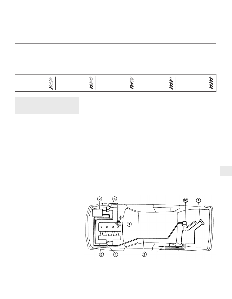
7 To minimise the escape into the
atmosphere of unburned hydrocarbons, an
evaporative emissions control system is fitted
to later models (see illustration). The fuel
tank filler cap is sealed, and a charcoal
canister, mounted underneath the front left-
hand wing, collects the petrol vapours
generated in the tank when the car is parked.
The canister stores them until they can be
cleared from the canister (under the control of
the fuel injection/ignition system ECU) via the
purge solenoid valve. When the valve is
opened, the fuel vapours pass into the inlet
tract, to be burned by the engine during
normal combustion.
8 To ensure that the engine runs correctly
when it is cold and/or idling, the ECU does not
1.7 Evaporative emissions control system
1 Fuel filler cap
2 Charcoal canister
3 Hose
4 Calibrated orifice
5 Hose
6 Solenoid valve
7 Coolant temperature
sensor
10 Safety valve