Peugeot 405 Haynes (petrol). Manual - part 15
1
General information and
precautions
The fuel system consists of a fuel tank
mounted under the rear of the car, a
mechanical fuel pump, and a carburettor. The
fuel pump is operated by an eccentric on the
camshaft, and is mounted on the rear of the
cylinder head. The air cleaner contains a
disposable paper filter element, and
incorporates a flap valve air temperature
control system; this allows cold air from the
outside of the car, and warm air from the
exhaust manifold, to enter the air cleaner in
the correct proportions.
The fuel pump lifts fuel from the fuel tank to
the carburettor via a filter located in the rear of
the engine compartment, and supplies it to the
carburettor via an anti-percolation chamber.
The anti-percolation chamber ensures that the
supply of fuel to the carburettor is kept at a
constant pressure, and is free of air bubbles.
Excess fuel is returned from the anti-
percolation chamber to the fuel tank.
The carburettor is either a Solex 34-34 Z1 or
Solex 32-34 Z2 twin-choke carburettor, or
Weber 36TLP single-choke carburettor (see
Section 11), mixture enrichment for cold starting
is by automatic choke on the Solex carburettor
and a cable-operated choke control on the
Weber carburettor. On the Solex carburettor a
vacuum-operated choke unloader, accelerator
pump and full load enrichener device are fitted
to govern the fuel requirements of the engine
over its full operating range.
The exhaust system consists of three or
four sections according to model. The front
pipe is in one or two sections; where it is in
two sections the rear section may be plain or
include a catalytic converter, where it is in one
section it may include a catalytic converter. All
models are fitted with an Intermediate pipe
and silencer, and a tailpipe and silencer. The
system is suspended throughout its entire
length by rubber mountings.
2
Air cleaner assembly -
removal and refitting
2
Removal
TU engine
1 Slacken the retaining clips (where fitted),
and disconnect the vacuum hose and
breather hose from the front of the air cleaner
housing-to-carburettor duct (see illustration).
Where the crimped-type Peugeot hose clips
are fitted, cut the clips and discard them; use
standard worm-drive hose clips on refitting.
2 Slacken the retaining clips, then lift the duct
off the top of the carburettor and air cleaner
housing. Disconnect the air temperature
control valve hose from the end of the duct,
and remove the duct from the engine
compartment
(see illustrations). Recover the
rubber sealing ring(s) from the top of the
carburettor and/or air cleaner housing (as
applicable).
3 Disconnect the inlet duct from the front of
the air cleaner housing, and remove the air
cleaner housing from the engine
compartment.
4 To remove the inlet duct assembly, undo
the retaining bolts securing the duct to the
left-hand wing valance, then release the
fastener securing the rear of the duct to the
cylinder head (see illustration). Disconnect
the hot-air inlet hose from the exhaust
manifold shroud, and remove the duct and
hose assembly from the engine compartment.
XU engine
5 Using an Allen key, unscrew the bolt
securing the air inlet duct to the top of the
carburettor. Loosen the clip and disconnect
the duct (see illustration).
6 Loosen the clip and disconnect the air inlet
duct from the filter housing top cover.
7 Release the clips and remove the top cover
from the air filter housing.
8 Remove the filter element from inside the
lower housing.
9 Release the lower housing from the
mounting rubbers then disconnect the inlet
duct and hoses as applicable.
Refitting
10 Refitting is a reversal of the removal
procedure, noting the following points:
a) Examine the rubber sealing ring(s) for
signs of damage or deterioration, and if
necessary renew. Note that, on some
models, the carburettor seal is fitted with
an O-ring; this should also be renewed if
it is damaged.
4A•2 Fuel/exhaust systems - carburettor models
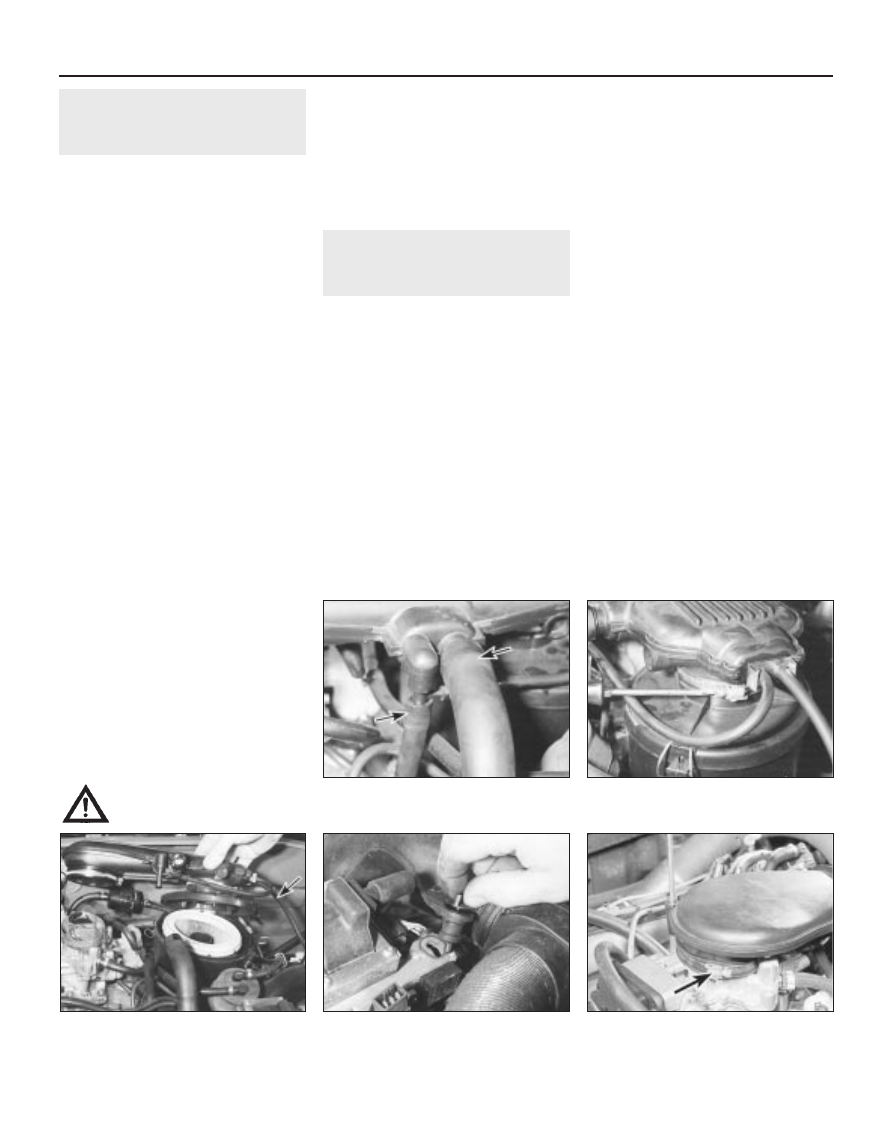
2.1 On the TU engine disconnect the
vacuum and breather hoses (arrowed)
from the front of the duct . . .
2.2b . . . and remove the duct,
disconnecting the air temperature control
valve hose (arrowed)
2.5 On the XU engine unscrew the bolt
securing the air inlet duct,
then loosen the clip
2.4 Undo the intake duct front bolt then
release the rear fastener, and remove the
duct and hose assembly (TU engine)
2.2a . . . slacken the retaining clips . . .
Warning: Many of the
procedures in this Chapter
require the removal of fuel lines
and connections, which may result in
some fuel spillage. Before carrying out
any operation on the fuel system, refer to
the precautions given in “Safety first!” at
the beginning of this manual, and follow
them implicitly. Petrol is a highly
dangerous and volatile liquid, and the
precautions necessary when handling it
cannot be overstressed.