Peugeot 405. Manual - part 60


  Главная      Peugeot     Peugeot 405 (1988-1997) - Service And Repair Manual Haynes


поиск по сайту            


содержание   ..  58  59  60  61   ..


Peugeot 405. Manual - part 60


Tailgate washer fluid reservoir

Disconnect the battery negative lead.
Open the tailgate, then turn the securing
clip and open the access panel at the right-
hand corner of the luggage compartment for
access to the reservoir.
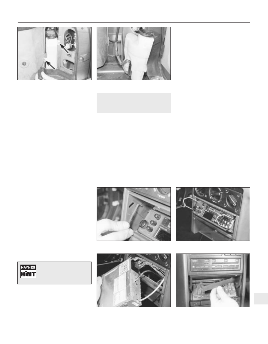
Remove the two securing screws, then lift
out the reservoir (see illustrations).
If the reservoir still contains fluid, empty out
the contents into a container, then disconnect
the wiring plug and the fluid hose from the
pump, and withdraw the reservoir.
10 Refitting is a reversal of removal.

Windscreen/headlight 
washer pump

Note: Prior to removing the pump, empty the
contents of the reservoir, or be prepared for
fluid spillage.
11 Disconnect the battery negative lead.
12 Disconnect the wiring connector and the
fluid hose from the pump, then carefully ease
the pump out of its sealing grommet in the
reservoir.
13 Refitting is a reversal of removal.

Tailgate washer pump

14 Disconnect the battery negative lead.
15 Remove the reservoir as described
previously in this Section.
16  Disconnect the wiring connector and the
fluid hose from the pump, then carefully ease
the pump out of its sealing grommet in the
reservoir.
17 Refitting is a reversal of removal.

Tailgate washer jet

18 Pull the washer jet from the rear of the
tailgate and disconnect the fluid hose.

19 Refitting is a reversal of removal.

20 Radio/cassette player -

removal and refitting

2

Radio/cassette player 
with DIN fittings

Removal

Disconnect the battery negative lead.
Carefully prise out and remove the small
plastic trim panels at each side of the
radio/cassette player (see illustration).
Insert the removal tools into the holes
provided at each side of the unit, until they
lock into position. This will release the
securing clips (see illustration).
Using the tools, pull the unit forwards from
the housing, and disconnect the wiring
connectors and the aerial lead (see
illustration)
.

Withdraw the unit from the facia.
Note that some units may have a bracket
and rubber buffer fitted to the rear panel. If a
new unit is being fitted, transfer these
components to the new unit. The buffer sets
the depth of the unit in the housing, and
prevents the security cover fouling the
cassette during insertion and ejection. These
parts are available from dealers if they are not
fitted.

Refitting

To refit the unit, reconnect the wiring plugs
and the aerial lead, and push the unit into
position until the securing clips lock. Ensure
that the wiring harness and aerial lead are
routed so that they cannot rub against the unit
casing.
Refit the plastic covers to each side of the
unit, and reconnect the battery negative lead.
Where applicable, to activate the unit, enter
the security code in accordance with the
manufacturer’s instructions.

Radio/cassette player 
with “Peugeot” fixings

Removal

10 Disconnect the battery negative lead.
11 Open the radio/cassette player cover
panel.
12 Working at the top of the unit, carefully
prise off the trim panel to expose the two
holes provided for the removal tools (see
illustration)
.
13 Two removal tools will now be required.
These tools can be made by cutting a
standard DIN radio/cassette player removal

Body electrical system  12•17

20.2  Remove the plastic trim panels from

the sides of the radio/cassette player . . .

20.12  Prise the trim panel from the top of

the radio/cassette player

20.4  . . . and withdraw the unit

20.3  . . . then insert the removal tools . . .

19.8b  . . . and lift out the tailgate washer

fluid reservoir

19.8a  Remove the two securing screws

(arrowed) . . .

12

Tie a length of string to the
end of the fluid hose to
prevent it from falling back
into the tailgate.

tool in half. Alternatively, use two pieces of
thin metal rod, with grooves cut in the ends to
engage with the retaining clips (see
illustration)
.
14 Insert the removal tools into the holes
provided above the unit, until they lock into
position. This will release the securing clips
(see illustration).
15 Using the tools, pull the unit forwards
from the housing, and disconnect the wiring
connectors and the aerial lead.
16 Withdraw the unit from the facia.

Refitting

17 Proceed as described in paragraph 7,
then refit the trim panel to the top of the unit,
and reconnect the battery negative lead.
18 Where applicable, to activate the unit,
enter the security code in accordance with the
manufacturer’s instructions.

21 Loudspeakers 

removal and refitting

2

Door-mounted loudspeakers

Disconnect the battery negative lead.
Remove the loudspeaker cover panel,
either by depressing the securing clip at the
lower edge of the panel, or by removing the
three securing screws from the edge of the
panel, as applicable (see illustrations).
Unscrew the securing screws, then
withdraw the loudspeaker from the door, and
disconnect the wiring plug (see illustration).
Refitting is a reversal of removal.

Facia-mounted loudspeakers -
models up to 1992

Disconnect the battery negative lead.

Carefully prise the loudspeaker cover panel
from the top of the facia (see illustration).
Remove the two securing screws, then
withdraw the loudspeaker from the facia, and
disconnect the wiring (see illustration).

Facia-mounted loudspeakers -
models from 1993

Disconnect the battery negative lead.
Carefully prise the loudspeaker from the top
of the facia, and disconnect the wiring plug
(see illustrations). The loudspeaker is
integral with the cover panel.
10 Refitting is a reversal of removal.

Rear parcel shelf-mounted
loudspeakers - Saloon models

11 Disconnect the battery negative lead.
12 Working in the luggage compartment, on
the underside of the parcel shelf, disconnect
the wiring from the loudspeaker.

21.9b  . . . and disconnect the wiring plug -

models from 1993

21.9a  Prise the loudspeaker 

from the facia . . .

21.7  . . . for access to the loudspeaker

screws (arrowed) - models up to 1992

12•18 Body electrical system

20.13  Make up two removal tools - note

slot (arrowed) in end of tool

21.2a  Release the 

securing clip . . .

21.6  Remove the loudspeaker cover panel

from the top of the facia . . .

21.3  Door-mounted loudspeaker securing

screws (arrowed)

21.2b  . . . and remove loudspeaker cover

panel from the door - models up to 1992

20.14  Insert the removal tools in the holes

at the top of the radio/cassette player 

13 Release the plastic securing clips, and
push the speaker up through the parcel shelf
into the vehicle interior. Remove the unit (see
illustration)
.
14 Refitting is a reversal of removal, but
ensure that the locating lug on the
loudspeaker engages with the hole in the
parcel shelf.

22 Radio aerial 

removal and refitting

3

Roof-mounted aerial

Note that the aerial mast can simply be
unscrewed from the base. To remove the
complete aerial assembly, proceed as follows.
Disconnect the battery negative lead.
Unclip the sun visors from the roof console.

Carefully prise the courtesy light assembly
from the console to expose the two roof
console front securing screws. Disconnect the
wiring plug and remove the light.
Similarly, prise the map reading light an the
light surround from the console to expose one
of the front securing screws. Disconnect the
wiring plug and remove the light.
Prise the blanking plate from the console
then, where applicable, push the sunroof
switch from the console.
Remove the two console screws exposed
by removal of the map reading light and
sunroof switch, then lower the console from
the roof, and disconnect the wiring plugs.
Prise the metal insulator from the base of
the aerial (see illustration).
Unscrew the securing nut and disconnect
the aerial lead, then withdraw the aerial from
the top of the roof.
10 Refitting is a reversal of removal.

Rear wing-mounted aerial

Saloon models

11 Fully retract the aerial.
12 Working in the luggage compartment,
remove the trim panels from the left-hand side
of the wing panel.
13 Disconnect the aerial lead connector and
the earth wire from the bottom of the aerial
(see illustration). On models with an electric
aerial, disconnect the motor wiring plug.
14 Unscrew the aerial mounting bracket
lower fixing bolt.
15 Working at the top of the aerial, unscrew
the ring nut securing the assembly to the top

of the rear wing. Recover the sealing grommet
(see illustrations).
16 Withdraw the aerial assembly down into
the luggage compartment.
17 Refitting is a reversal of removal.

Estate models

18 The procedure is as described previously
for Saloon models, but the upper end of the
aerial is retained by a grommet arrangement
instead of a ring nut. When removing the
aerial, simply pull the top of the aerial down
through the grommet (see illustrations).

23 Anti-theft alarm system -

general information

Note: This information is applicable only to the
anti-theft alarm system fitted by Peugeot as
standard equipment.

Body electrical system  12•19

22.13  Aerial lead (A) and earth wire (B) -

Saloon (rear wing-mounted manual aerial)

22.18a  Disconnecting aerial motor wiring

plug - Estate (rear wing-mounted aerial)

22.15b  . . . and recover sealing grommet -
Saloon (rear wing-mounted manual aerial)

22.15a  Unscrew the ring nut . . .

22.8  Roof-mounted radio aerial metal

insulator (arrowed)

21.13  Removing the rear loudspeaker -

Saloon models

12

22.18b  Unscrew the aerial motor 

securing bolt . . .

22.18c  . . . and withdraw aerial assembly -

Estate (rear wing-mounted aerial)

General

Some models in the range are fitted with an
anti-theft alarm system as standard equipment.
The alarm is automatically armed and disarmed
using the remote central locking transmitter
(where applicable). When the system is
activated, the alarm indicator light, located on
the facia, will flash continuously. In addition to
the alarm function, the system also
incorporates an engine immobiliser.
Additionally, certain petrol engine models
are fitted with a coded engine immobiliser
device, operated by a key pad in the centre
console.

Anti-theft alarm system

Early models

Note that if the doors are operated using
the key, the alarm will not be armed or
disarmed (as applicable). Locking the doors
with the central locking remote transmitter is
the only means of activating the alarm system.
The alarm system protects the doors and
boot or tailgate, as applicable.
Should the alarm system become faulty, the
vehicle should be taken to a Peugeot dealer
for examination.

Later models

Note that if the doors are operated using
the key, the alarm will not be armed or
disarmed (as applicable). If for some reason
the remote central locking transmitter fails
whilst the alarm is armed, the vehicle must be
unlocked using the key. In this case, the alarm
system will activate, and must be disarmed
using the master switch (see paragraph 8).
The alarm system has switches on the
bonnet, tailgate and each of the doors. It also
has ultrasonic sensing, which detects
movement inside the vehicle, via sensors
mounted on either side of the vehicle interior. If
required, the ultrasonic sensing facility can be
switched off, whilst retaining the switched side
of the system. To switch off the ultrasonic
sensing, with the ignition switch off, depress
the alarm switch (mounted on the right of the
steering column) until the alarm indicator light
on the facia is continuously lit. Now, when the
doors are locked using the remote central
locking transmitter, and the alarm is armed,
only the switched side of the alarm system is
operational (and the alarm indicator light will
revert to its flashing mode). This facility is
useful, as it allows you to leave the
windows/sunroof open, and still arm the alarm.
If the windows/sunroof are left open with the
ultrasonic sensing not switched off, the alarm
may be falsely triggered by a gust of wind.
To deactivate the complete alarm system, a
master switch is provided in the engine
compartment, behind the left-hand headlight.
The switch is operated by a dedicated key,
and is protected by a plastic cover.
Should the alarm system become faulty, the
vehicle should be taken to a Peugeot dealer
for examination.

Coded engine immobiliser

10 This device cuts out the engine
management system, and prevents the engine
from being started unless a confidential code
is keyed into the pad located in the centre
console.
11 The code can be chosen by the owner,
and full details are given in the vehicle
handbook.
12 When the ignition is turned on, if the green
light on the key pad is illuminated, the system
is not working, and the engine can be started
normally. If the red light is illuminated, the
system is working (the engine cannot be
started, and the alarm will sound if starting is
attempted).
13 To de-activate the system, enter the
correct code, which should be confirmed by
four flashes from the green light, and four
beeps. The red light should go out, and the
engine can them be started.
14 If the wrong code is entered, the red light
will stay on, and the engine cannot be started.

Disconnecting the battery

Early models

15 If the battery has been disconnected,
when it is reconnected, the alarm will be
activated.
16 The alarm must be de-activated using the
remote central locking transmitter.

Later models

17 The following precautions should be
observed when disconnecting and
reconnecting the battery leads on a vehicle
equipped with an alarm system.
18 Before disconnecting the battery, de-
activate the alarm siren, using the dedicated
key.
19 When reconnecting the battery, as soon
as the battery is connected, the alarm is
automatically activated. Use the remote
transmitter to turn off the alarm, then activate
the alarm siren using the dedicated key.

24 Air bag system - general

information, precautions and
system de-activation

General information

A driver’s side air bag is fitted as standard
equipment on later models, and is an option
on all other models. The air bag is fitted in the
steering wheel centre pad.
The system is armed only when the ignition
is switched on, however, a reserve power
source maintains a power supply to the
system in the event of a break in the main
electrical supply. The system is activated by a

“g” sensor (deceleration sensor), and is
controlled by an electronic control unit which
is integral with the steering wheel.
The air bag is inflated by a gas generator,
which forces the bag out from its location in
the steering wheel.

Precautions

General precautions

The following precautions must

be

observed when carrying out work on a vehicle
equipped with an air bag.

a) Do not disconnect the battery with the

engine running.

b) Before carrying out any work in the vacinity

of the air bag, removal of any of the air bag
components, or any welding work on the
vehicle, de-activate the system as
described in the following sub-Section.

c) Do not attempt to test any of the air bag

system circuits using test meters or any
other test equipment.

d) If the air bag warning light comes on, or

any fault in the system is suspected,
consult a Peugeot dealer without delay.
Do not attempt to carry out fault
diagnosis, or any dismantling of the
components.

Precautions to be taken when
handling an air bag

a) Transport the air bag by itself, bag

upward.

b) Do not put your arms around the air bag.
c) Carry the air bag close to the body, bag

outward.

d) Do not drop the air bag or expose it to

impacts.

e) Do not try to dismantle the air bag unit.
f) Do not connect any form of electrical

equipment to any part of the air bag circuit.

Precautions to be taken when storing
an air bag unit

a) Store the unit in a cupboard with the air

bag upward.

b) Do not expose the air bag to

temperatures above 80ºC.

c) Do not expose the air bag to flames.
d) Do not attempt to dispose of the air bag -

consult a Peugeot dealer.

e) Never refit an air bag which is known to

be faulty or damaged.

De-activation of air bag system

The system must be de-activated before
carrying out any work on the air bag
components or surrounding area.

a) Switch off the ignition.
b) Remove the ignition key.
c) Switch off all electrical equipment.

12•20 Body electrical system

Warning: Do not forget the
immobiliser code - if the correct
code cannot be entered, the
engine management electronic

control unit must be renewed.

Warning: The following
precautions must be observed
when working on vehicles
equipped with an air bag

system, to prevent the possibility of
personal injury.


содержание   ..  58  59  60  61   ..