содержание .. 51 52 53 54 ..
Peugeot 405. Manual - part 53
Later models
36 Remove the small screws securing the
two halves of the key/transmitter casing
together. Remove the two batteries, noting
which way round they are fitted.
37 Fit the new batteries, ensuring that they
are fitted the correct way round. Clip the two
halves of the casing back together and refit
the securing screw.
21 Electric window
components -
removal and refitting
3
Electronic control unit
Removal
1 Remove the driver’s door inner trim panel
as described in Section 13.
2 The control unit is clipped to a bracket on the
rear of the door trim panel (see illustration).
3 Unclip the control unit and withdraw it from
the panel.
Refitting
4 Refitting is a reversal of removal. Refit the
door trim panel as described in Section 13.
Window switches
5 Refer to Chapter 12.
Window regulator motors
6 The regulator motors are integral with the
regulator assemblies, and cannot be obtained
separately.
7 Removal and refitting details for the
regulator assemblies are given in Section 15.
22 Exterior mirrors and
associated components -
removal and refitting
3
General
1 A number of different types of rear view
mirror may be encountered, according to
model, and date of manufacture.
2 The following paragraphs provide a guide
to all types.
Mirror
Removal
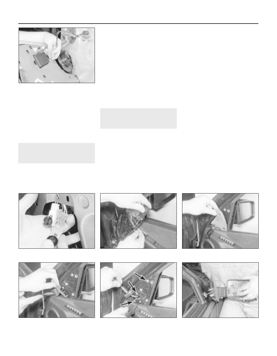
3 On models with electric mirrors, remove the
door inner trim panel (Section 13), then peel back
the plastic sealing sheet from the door for access
to the mirror wiring connector(s). Disconnect the
wiring connectors (see illustration).
4 If not already done, prise the mirror trim
plate from the inside front corner of the door.
Where applicable, loosen the clamp screw,
and release the adjuster knob from the trim
plate (see illustration).
5 Where applicable, prise the sealing strip
and the grommet from the adjuster linkage
aperture in the door for access to the lower
mirror securing screws (see illustrations).
6 Remove the four securing screws, and
withdraw the mirror from the door (see
illustrations). Where applicable, feed the
wiring up through the door, noting its routing.
Refitting
7 Refitting is a reversal of removal, but where
applicable refit the door inner trim panel with
reference to Section 13.
Mirror glass
Removal
8 Various methods have been used to retain
the glass. On some mirrors, the glass cannot
be removed from the housing, and the
complete mirror unit must be renewed. The
mirror glass may be stuck using adhesive
pads; on later types of mirror, the glass may
be held by a wire clip, or by a locking ring.
9 To remove a mirror glass secured by a
locking ring, tilt the glass fully upwards, then
insert a screwdriver at the lower edge of the
glass and locate the locking ring. Lever the
locking ring towards the door of the vehicle to
release the glass (see illustration).
22.6b . . . and withdraw the mirror
11•14 Bodywork and fittings
21.2 Disconnecting wiring plug from the
electric windows electronic control unit
22.4 Loosen the clamp screw and release
mirror adjuster knob from the trim plate
22.6a Remove the four
securing screws . . .
22.5b . . . and the grommet
22.5a Prise off the sealing strip . . .
22.3 Disconnecting the door mirror
wiring connectors