содержание .. 30 31 32 33 ..
Peugeot 405. Manual - part 32
1
General information and
precautions
The fuel system consists of a fuel tank
(which is mounted under the rear of the car,
with an electric fuel pump immersed in it), a
fuel filter, fuel feed and return lines, and the
throttle body assembly (which incorporates
the single fuel injector and the fuel pressure
regulator). In addition, there is an Electronic
Control Unit (ECU) and various sensors,
electrical components and related wiring. The
air cleaner contains a disposable paper filter
element, and incorporates a flap valve air
temperature control system. This allows cold
air from the outside of the car and warm air
from around the exhaust manifold to enter the
air cleaner in the correct proportions.
Refer to Section 7 for further information on
the operation of each fuel injection system,
and to Section 18 for information on the
exhaust system.
Throughout Part B, it is occasionally
necessary to identify vehicles by their engine
codes rather than by engine capacity. Refer to
the relevant Part of Chapter 2 for further
information on engine code identification.
Note: Residual pressure will remain in the
fuel lines long after the vehicle was last used.
When disconnecting any fuel line, first
depressurise the fuel system as described in
Section 8.
2
Air cleaner assembly and
inlet ducts - removal and
refitting
2
Refer to Chapter 4A, Section 2, substituting
“throttle body” for all references to the
carburettor.
3
Air cleaner air temperature
control system - information
and component renewal
2
Refer to Chapter 4A, Section 3, substituting
“throttle body” for all references to the
carburettor.
4
Accelerator cable - removal,
refitting and adjustment
2
Note: For automatic transmission models
refer to Chapter 7B.
Removal and refitting
1 Refer to Chapter 4A, Section 7 substituting
“throttle body” for all references to the
carburettor. Adjust the cable as described
below.
Adjustment
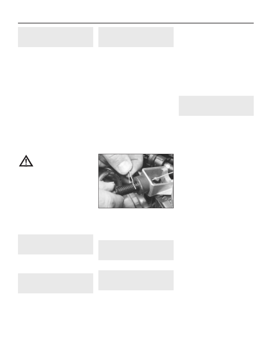
2 Remove the spring clip from the accelerator
outer cable then, ensuring that the throttle
cam is fully against its stop, gently pull the
cable out of its grommet until all free play is
removed from the inner cable.
3 With the cable held in this position, ensure
that the flat washer is pressed securely
against the grommet, then fit the spring clip to
the third outer cable groove visible in front of
the rubber grommet and washer (see
illustration). This will leave a fair amount of
freeplay in the inner cable which is necessary
to ensure correct operation of the idle control
stepper motor (see Section 14).
4 Have an assistant depress the accelerator
pedal and check that the throttle cam opens
fully and returns smoothly to its stop.
5
Accelerator pedal -
removal and refitting
2
Refer to Chapter 4A, Section 8.
6
Unleaded petrol - general
information and usage
Note: The information given in this Chapter is
correct at the time of writing. If updated
information is thought to be required, check
with a Peugeot dealer. If travelling abroad,
consult one of the motoring organisations (or a
similar authority) for advice on the fuel
available.
The fuel recommended by Peugeot is given
in the Specifications Section of this Chapter,
followed by the equivalent petrol currently on
sale in the UK.
All Peugeot 405 single-point injection
models are designed to run on fuel with a
minimum octane rating of 95 (RON). All
models are equipped with catalytic
converters, and therefore must be run on
unleaded fuel only. Under no circumstances
should leaded (UK “4-star”) fuel be used, as
this may damage the catalytic converter.
Super unleaded petrol (98 octane) can also
be used in all models if wished, though there
is no advantage in doing so.
7
Fuel injection systems -
general information
Note: The fuel injection ECU is of the “self-
learning” type, meaning that as it operates, it
also monitors and stores the settings which
give optimum engine performance under all
operating conditions. When the battery is
disconnected, these settings are lost and the
ECU reverts to the base settings programmed
into its memory at the factory. On restarting,
this may lead to the engine running/idling
roughly for a short while, until the ECU has re-
learned the optimum settings. This process is
best accomplished by taking the vehicle on a
road test (for approximately 15 minutes),
covering all engine speeds and loads,
concentrating mainly in the 2500 to 3500 rpm
region.
Fenix 1B system
1 The Fenix 1B system is an integrated
single-point fuel injection/ignition system.
Using inputs from various sensors, the
electronic control unit computes the optimum
fuel injector pulse duration, and ignition
advance setting, to suit the prevailing engine
operating conditions.
2 The electronic control unit receives signals
from the following sensors.
a) Engine speed/position sensor.
b) Manifold absolute pressure (MAP) sensor.
c) Inlet air temperature sensor.
d) Throttle position sensor.
e) Coolant temperature sensor.
f) Oxygen sensor.
3 The fuel injection unit houses the fuel
injector, the fuel pressure regulator, the
throttle position switch, and the idle speed
control valve. The single fuel injector injects
fuel upstream of the throttle valve.
4 Idle speed is controlled by the electronic
control unit, via the idle speed control valve.
5 The oxygen sensor allows the electronic
control unit to control the air/fuel mixture
within very fine limits, to enable the use of a
catalytic converter.
6 All the information supplied to the
electronic control unit is computed and
compared with pre-set values stored in the
4B•2 Fuel/exhaust systems - single-point fuel injection models
4.3 Adjust the accelerator cable as
described in text
Warning: Many of the
procedures in this Chapter
require the removal of fuel lines
and connections, which may
result in some fuel spillage. Before
carrying out any operation on the fuel
system, refer to the precautions given in
“Safety first!” at the beginning of this
manual, and follow them implicitly. Petrol
is a highly dangerous and volatile liquid,
and the precautions necessary when
handling it cannot be overstressed.