Peugeot 405. Manual - part 28


  Главная      Peugeot     Peugeot 405 (1988-1997) - Service And Repair Manual Haynes


поиск по сайту            


содержание   ..  26  27  28  29   ..


Peugeot 405. Manual - part 28


Heater/ventilation control unit -
models from 1993

Note: Refer to the facia removal procedure in
Chapter 11 for relevant illustrations of facia
housing removal.

Removal

13 Disconnect the battery negative lead.
14 Remove the centre console (Chapter 11).
15 Open the ashtray cover, and unscrew the
two screws located at the bottom of the
ashtray housing.
16 Where applicable, remove the radio/
cassette player with reference to Chapter 12.
On models not fitted with a radio/cassette
player, prise out the oddments tray.
17 Remove the two securing screws from the
top of the radio/cassette player/oddments
tray housing, then withdraw the housing from
the facia. Where applicable, disconnect the
wiring plug(s) from the rear of the housing.
18 Prise the blanking plate from the top
corner of the facia centre ventilation nozzle
housing. Remove the now-exposed securing
screw.
19 Remove the four housing securing screws
located under the heater control panel. Two
screws are accessible from the front of the
housing, and two screws from underneath.
20 Carefully prise the switches from below
the centre facia ventilation nozzles to reveal
the remaining housing securing screw.
Remove the screw.
21 Pull the housing forwards, and disconnect
the wiring from the clock, then withdraw the
housing.

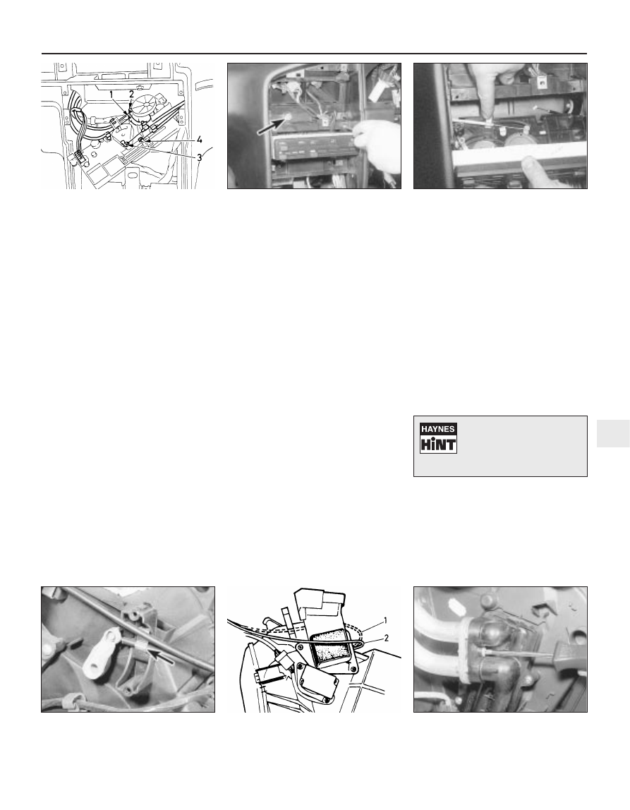
22 Remove the two securing screws located
at the top of the heater control unit (see
illustration)
.
23 Pull the control unit forwards from the
facia.
24 Working at the top of the unit, disconnect
the two control cables and the wiring plug.
The cables can be disconnected after
releasing the metal spring clips securing the
cable sheaths to the control unit (see
illustration)
. Note the cable locations to
ensure correct refitting.
25 Working under the unit, disconnect the
remaining control cable, then withdraw the
unit.

Refitting

26 Refitting is a reversal of removal, ensuring
that the cables are correctly routed and
securely reconnected.

Heater/ventilation control cables

Removal

27 Disconnect the cables from the heater
control unit by removing the control unit as
described previously in this Section.
28 With the heater control unit removed,
access can be gained to the cable
connections on the heater unit, behind the
facia  (see illustration). Access may be
improved by removing surrounding panels
with reference to Chapter 11.
29 Note the locations and routing of the
cables to ensure correct refitting.

Refitting

30 Refitting is a reversal of removal, bearing
in mind the following points.

a) The cables are of a preset length, and no

adjustment is required; small adjustments
can be made by repositioning the cable
sheaths in the securing clips.

b) When reconnecting the air inlet flap cable,

the cable must be routed around the air
inlet duct, not behind it  (see illustration).

c) Refit the heater control unit as described

previously in this Section.

Heater matrix

Removal

31 Remove the complete facia assembly as
described in Chapter 11.
32 Drain the cooling system (Chapter 1).

33 Place a tray under the heater pipe
connections in the passenger compartment,
and place absorbent cloths on the carpet, in
case of coolant spillage.
34 Where applicable, unscrew the bolt
securing the heater pipes.
35 Unscrew the screw(s) securing the heater
pipes to the connector on the heater matrix
(see illustration).

Cooling, heating and ventilation systems  3•7

9.24  Disconnect the control cables from

the heater control unit - models from 1993

9.35  Remove the screw securing the

heater pipes to the matrix connector

9.30  Correct routing of heater air inlet flap

control cable - models up to 1992

9.28  Heater control cable metal spring clip

(arrowed) at heater unit

9.22  Remove the heater control unit
securing screws - models from 1993

9.11  Heater control cables reconnection

sequence - models up to 1992

3

1  Incorrect routing

2  Correct routing

To avoid draining the
cooling system, clamp the
coolant hoses as close as
possible to the heater matrix

pipes, in the engine compartment.

36 To remove the matrix from the heater
assembly, unscrew the two securing screws,
then carefully withdraw the matrix from its
housing in the heater assembly, moving the
heater pipes aside as the matrix is withdrawn.
Recover the O-rings from the matrix pipe
connections (see illustrations).

Refitting

37 Refitting is a reversal of removal, bearing
in mind the following points.

a) Use new O-rings when reconnecting the

heater matrix pipes to the connector on
the heater matrix.

b) Refit the facia assembly (see Chapter 11).
c) On completion, refill (or top-up) the

cooling system as described in Chapter 1.

Complete heater assembly -
models without air conditioning

Removal

38 Remove the complete facia assembly as
described in Chapter 11.

39 Drain the cooling system (see Chapter 1).
40 Working in the engine compartment,
disconnect the coolant hoses from the heater
matrix (it may be necessary to remove
surrounding components for access on some
models).
41 Where applicable, remove the securing

screws, and remove the plastic shields from
the heater air inlet, and the windscreen wiper
motor in the scuttle at the rear of the engine
compartment. This will expose the heater
securing bolts  (see illustration).
42 Working in the scuttle, unscrew the heater
securing bolts.
43 Unclip the air ducts connecting the heater
assembly to the floor heating.
44 Place a tray under the heater pipe
connections in the passenger compartment,
and place absorbent cloths on the carpet, in
case of coolant spillage.
45 Where applicable, unscrew the bolt
securing the heater pipes.
46 Unscrew the screw(s) securing the heater
pipes to the connector on the heater matrix.
47 Unscrew the bolt from the lower right-hand
corner of the heater unit (see illustration).
48 Disconnect the wiring plugs from the
heater assembly, and release the wiring
harnesses from any clips. Note the routing of
the wiring to ensure correct refitting.
49 Pull the heater assembly back from the
bulkhead to disengage the matrix connector
from the heater pipes. Withdraw the heater
assembly from the vehicle (complete with the
control unit), being prepared for coolant
spillage. Recover the O-rings from the matrix
pipe connections.

Refitting

50 Refitting is a reversal of removal, bearing
in mind the following points.

a) Use new O-rings when reconnecting the

heater matrix pipes to the connector on
the heater matrix.

b) Ensure that the wiring harnesses are

routed as noted before removal.

c) Refit the facia assembly as described in

Chapter 11.

d) On completion, refill (or top-up) the

cooling system as described in Chapter 1.

Complete heater assembly -
models with air conditioning

Removal

51 Before carrying out any work, have the air
conditioning refrigerant circuit discharged by
a qualified air conditioning specialist.
52 Working in the engine compartment,
unscrew the nuts securing the clamp to the
evaporator refrigerant pipes at the engine
compartment bulkhead.
53 Slide the clamp back along the pipes,
away from the bulkhead.
54 Pull the two refrigerant pipes from the
relief valve on the bulkhead.
55 Proceed as described in paragraphs 38 to
49 inclusive, but note that it will be necessary
to disconnect the wiring plugs from the air
conditioning electrical components mounted
on the heater assembly. Note the locations of
the connectors, and the routing of the wiring
harnesses.

Refitting

56 Refitting is a reversal of removal, noting
the following points.

a) Ensure that all wiring plugs are correctly

reconnected, and that the wiring is routed
as noted before removal.

b) Use new O-rings when reconnecting the

heater matrix pipes to the connector on
the heater matrix.

c) Use new O-rings when reconnecting the

refrigerant pipes to the relief valve at the
bulkhead.  

d) On completion, refill (or top-up) the

cooling system as described in Chapter 1,
and have the refrigerant circuit recharged
by a qualified air conditioning specialist.

3•8 Cooling, heating and ventilation systems

9.36a  Remove the two 

securing screws . . .

9.36c  . . . and recover the O-rings from the

pipe connections

9.47  Heater unit lower right-hand securing

bolt (arrowed)

9.41  Plastic shield securing screws (1) and

heater securing bolt (2)

9.36b  . . . then withdraw the 

heater matrix . . .

To avoid draining the
cooling system, clamp the
coolant hoses as close as
possible to the heater matrix

pipes, in the engine compartment.

Warning: Do not attempt to
remove the heater unit until the
air conditioning refrigerant
circuit has been discharged by a
qualified expert.

Heater blower motor

Removal

57 Working under the passenger’s side of the
facia, release the securing clips and withdraw
the carpet trim panel from under the facia.
58 If desired, to improve access, remove the
glovebox as described in Chapter 11.
59 Reach up under the facia and disconnect
the blower motor wiring plug. Where
applicable, release the wiring from the clip(s)
on the motor casing (see illustration).
60 Unscrew the three securing screws from
the bottom of the motor casing, and withdraw
the motor assembly (see illustration).

Refitting

61 Refitting is a reversal of removal.

Heater blower control module

Removal

62 The control module assembly is located in
the motor casing.

63 Remove the blower motor as described
previously in this Section.
64 Where applicable, pull the rubber
grommet from the motor casing, and
disconnect the wiring from the motor (see
illustration)
. Note the wire locations to ensure
correct refitting.
65 Working through the fan blades, remove
the screws, and/or release the clips securing
the motor assembly to the casing (release the
clips using a pair of pliers or a screwdriver,
depending on the type of clip encountered)
(see illustrations).
66 Withdraw the motor/fan blade assembly
from the casing (see illustration).
67 Disconnect the wiring plug from the rear
of the control module (see illustration).
68 Remove the two securing screws, and
withdraw the control module (see
illustrations)
.

Refitting

69 Refitting is a reversal of removal.

10 Air conditioning system -

general information and
precautions

General information

An air conditioning system is available on
certain models up to 1992, and on all models
from 1993. It enables the temperature of
incoming air to be lowered, and also
dehumidifies the air, which makes for rapid
demisting and increased comfort.
The cooling side of the system works in the
same way as a domestic refrigerator.
Refrigerant gas is drawn into a belt-driven
compressor, and passes into a condenser
mounted on the front of the radiator, where it
loses heat and becomes liquid. The liquid
passes through an expansion valve to an
evaporator, where it changes from liquid
under high pressure to gas under low

Cooling, heating and ventilation systems  3•9

9.64  Pull the rubber grommet from the

motor casing for access to the wiring

9.66  . . . then withdraw motor from casing

9.65b  . . . and release the clips . . .

9.65a  Remove the securing screws . . .

9.60  Withdrawing the heater blower motor

9.59  Disconnect the blower motor 

wiring plug

3

9.67  Disconnect the wiring plug . . .

9.68a  . . . then remove the 

securing screws . . .

9.68b  . . . and withdraw the control module

pressure. This change is accompanied by a
drop in temperature, which cools the
evaporator. The refrigerant returns to the
compressor, and the cycle begins again.
Air blown through the evaporator passes to
the air distribution unit, where it is mixed with
hot air blown through the heater matrix to
achieve the desired temperature in the
passenger compartment.
The heating side of the system works in the
same way as on models without air
conditioning (see Section 9).
The operation of the system is controlled
electronically by the “Bitron” control unit,
which controls the electric cooling fan(s), the
compressor, and the facia-mounted warning
light. Any problems with the system should be
referred to a Peugeot dealer.

Precautions

When an air conditioning system is fitted, it
is necessary to observe special precautions
whenever dealing with any part of the system,

or its associated components. If for any
reason the system must be disconnected,
entrust this task to your Peugeot dealer or a
refrigeration engineer.

The refrigerant is potentially dangerous,
and should only be handled by qualified
persons. If it is splashed onto the skin, it can
cause frostbite. It is not itself poisonous, but
in the presence of a naked flame (including a
cigarette) it forms a poisonous gas.
Uncontrolled discharging of the refrigerant is
dangerous, and potentially damaging to the
environment.
Do not operate the air conditioning system
if it is known to be short of refrigerant, as this
may damage the compressor.

11 Air conditioning system

components - removal and
refitting

4

The only operation which can be carried out

easily without discharging the refrigerant is
renewal of the compressor drivebelt. This is
described in Chapter 1. (The “Bitron”
temperature sensor may be renewed using
the information in Section 6.) All other
operations must be referred to a Peugeot
dealer or an air conditioning specialist.

If necessary, the compressor can be

unbolted and moved aside, without
disconnecting its flexible hoses, after
removing the drivebelt.

3•10 Cooling, heating and ventilation systems

Warning: Do not attempt to
open the refrigerant circuit.
Refer to the precautions given
in Section 10.

Warning: The refrigeration
circuit may contain a liquid
refrigerant (Freon), and it is
therefore dangerous to

disconnect any part of the system without
specialised knowledge and equipment.


содержание   ..  26  27  28  29   ..