Peugeot 205. Manual - part 46


  Главная      Peugeot     Peugeot 205 - Service And Repair Manual Haynes


поиск по сайту            


содержание   ..  44  45  46  47   ..


Peugeot 205. Manual - part 46


13 Remove the screws and withdraw the
centre vents.
14 Using a screwdriver through the steering
column lower shroud, unscrew the visor
locating studs.
15 Remove the side screw, then lift away the
visor.
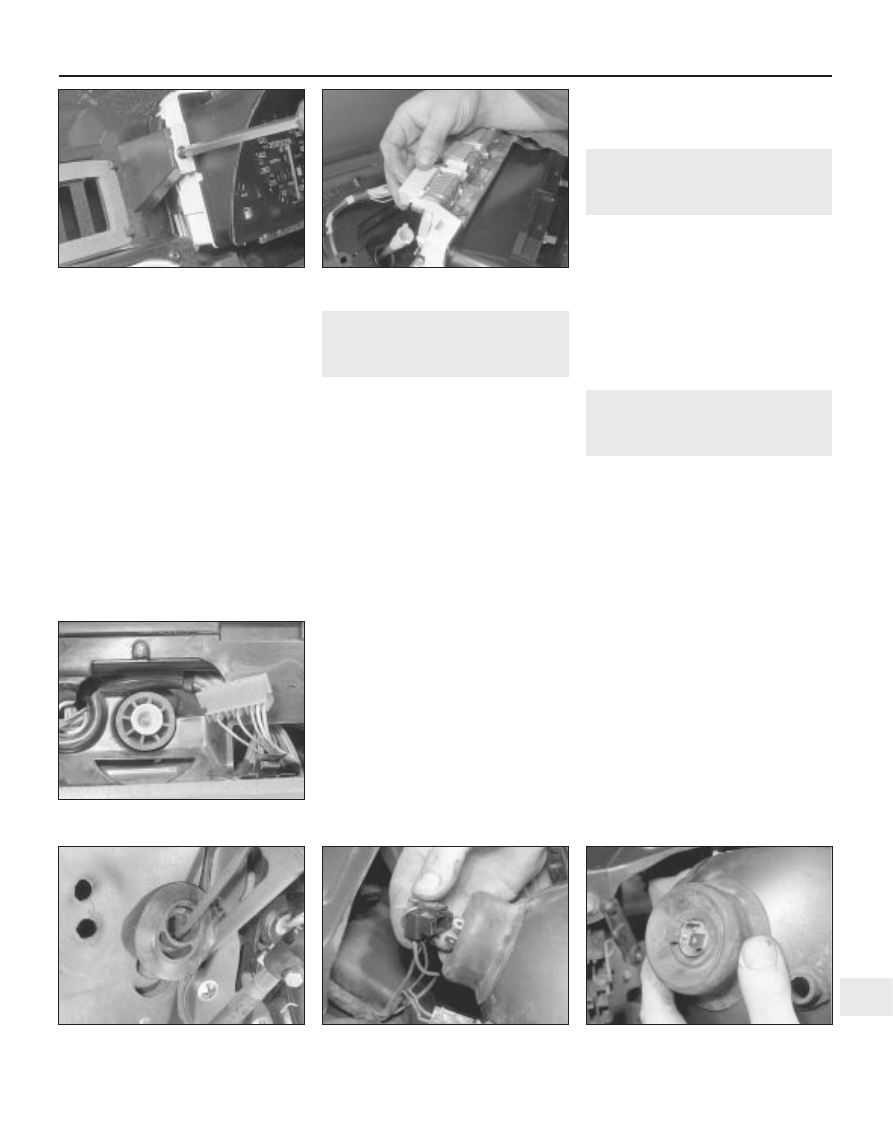
16 Remove the mounting screws from each
side of the instrument panel (see illustration)
17 Tilt the instrument panel and disconnect
the wiring plugs, noting their locations (see
illustration)

18 Disconnect the speedometer cable by
squeezing the end fitting. Remove the
instrument panel. If necessary, the individual
components can be removed for repair or
renewal.

Refitting

19 On all models, refitting is a reversal of
removal.

6

Clock - removal and refitting

1

Removal

Pre-1988 models

Disconnect the battery negative lead.
Using a small screwdriver, carefully prise
the clock from its location in the facia.
Disconnect the clock wiring and remove the
unit.

1988 models onward

Disconnect the battery negative lead.
Remove the trapezium-shaped coin
compartment or cover from the top of the
facia by lifting the bottom edge.
Pull off the heater control knobs, using card
or thick cloth and pliers on the central bars.
Remove the screws beneath the control
knobs, and withdraw the upper front panel
surround.
Open and remove the ashtray.
Unclip the bottom of the clock surround
and remove it.
10 Remove the oddments tray, or if fitted, the
radio, as described in Section 22.
11 Remove the screws and withdraw the
lower front panel surround by releasing the
bottom edge first.
12 Disconnect the wiring plug from the rear
of the clock, then release the clock from the
lower front panel surround.

Refitting

13 On all models, refitting is a reversal of
removal.

7

Speedometer cable - renewal

2

Disconnect the speedometer cable from
the transmission by removing the retaining
bolt or rubber plug. 
Remove the instrument panel, as described
in Section 5. 
Prise the rubber grommet from the
bulkhead beneath the facia (see
illustrations)

Remove the retaining clips, where fitted,
and withdraw the speedometer cable. 
Refitting is a reversal of removal.

8

Bulbs (exterior lights) -
renewal

2

General

With all light bulbs, remember that if they
have just been in use, they may be very hot.
Switch off the power before renewing a bulb.
With quartz halogen bulbs (headlights and
similar applications), use a tissue or clean
cloth when handling the bulb; do not touch
the bulb glass with the fingers. Even small
quantities of grease from the fingers will
cause blackening and premature failure. If a
bulb is accidentally touched, clean it with
methylated spirit and a clean rag.
Unless otherwise stated, fit the new bulb by
reversing the removal operations.

Bulb renewal

Headlight

Where fitted, remove the cover from the
rear of the headlight. 
Pull the connector from the bulb (see
illustration)

Remove the rubber cover, noting that the
water drain hole is at the bottom (see
illustration)

Body electrical system  12•9

12

5.16  Removing the instrument panel

mounting screws on later models . . .

5.17  . . . and disconnecting the wiring

plugs

7.3a  Speedometer cable end with

instrument panel removed

7.3b  Speedometer cable grommet on the

bulkhead

8.5 Pull off the connector . . .

8.6 . . . remove the rubber cover . . .

Release the spring clips and withdraw the
bulb (see illustrations)
Fit the new bulb with the locating tab
uppermost.

Front parking lights 

Pull the bulbholder from the rear of the
headlight then depress and twist the bulb to
remove it (see illustration).

Front direction indicator

10 Turn the bulbholder anti-clockwise and
withdraw it from the rear of the light (see
illustration)

11 Depress and twist the bulb to remove it
(see illustration)

Front direction indicator side repeater

12 On early models, reach up behind the
front wing, squeeze the plastic tabs together
and push out the light. On later models, turn
the light anti-clockwise and withdraw it from
the front wing (see illustration).
13 Disconnect the wiring, remove the end
cap, and extract the bulb:
14 When refitting the early type, position the

light so that the location peg enters the hole in
the front wing.

Front driving light (GTI models) 

15 Remove the two lens surround retaining
screws and withdraw the surround, lens and
reflector (see illustration)
16 Release the spring clips and remove the
bulb assembly (see illustration)
17 Detach the bulb feed wire at the
connector.

Rear light cluster bulbs

18 Remove the lens upper retaining screws
then tilt the lens back and release it from the
lower tabs (see illustrations)
19 Depress and twist the bulb to remove it
(see illustration)

Rear foglight 

20 Remove the screws and withdraw the lens
(see illustration)

12•10 Body electrical system

8.7a  . . . release the spring clips . . .

8.7b  . . . and withdraw the headlight bulb

8.9  Removing the front parking light

bulbholder

8.16  . . . then release the spring clips and

remove the bulb assembly

8.18a  Remove the rear light cluster

screws . . .

8.18b . . . and release the lens from the

tabs

8.11 . . . and extract the bulb

8.10  Remove the front direction indicator

light bulbholder . . .

8.12  Removing the front direction

indicator side repeater on later models

8.15 On GTI models, remove the driving

light lens surround, lens and reflector . . .

21 Depress and twist the bulb to remove it
(see illustration)

Number plate light 

22 Twist off the lens (see illustration)

23 Depress and twist the bulb to remove it
(see illustration)

Reversing light (1991 models onward)

24 On later models, a single reversing light is
mounted in the rear valance, instead of the
twin lights in the rear light clusters fitted to
previous models.
25 Bulb renewal is as described previously
for the rear foglight bulb.

9

Bulbs (interior lights) -
renewal

1

General

See Section 8, paragraphs 1 and 3.
Some switch illumination/pilot bulbs are
integral with their switches and cannot be
renewed separately.

Bulb renewal

Interior light

Prise the light from the console (see
illustration)

Extract the festoon type bulb from within
the light unit. 

Map reading light

Prise the light from the console and extract
the festoon type bulb (see illustration)

Instrument panel bulbs 

Remove the instrument panel, as described
in Section 5. 
Two types of bulb are fitted. Pull out the
square type bulbholder and remove the
wedge type bulb (see illustration). Twist the
round type bulbholder through 90° to remove
it, but on this type the bulb cannot be
separated from the holder.

Glovebox light 

On pre-1988 models, remove the switch,
with reference to Section 4, then depress and
twist the bulb to remove it.
On 1988 models onward, open the
glovebox and prise out the light. Remove the
festoon-type bulb from the terminals.

Clock illumination bulb

10 Remove the clock as described in Sec-
tion 6. 
11 Twist the bulbholder from the rear of the
clock, then remove the bulb from the holder
(see illustration)

Body electrical system  12•11

12

8.19  Removing a rear light cluster bulb

8.20  Remove the rear foglight lens . . .

8.21 . . . and extract the bulb

9.5  Removing the map reading light and

extract the bulb

9.3  Prise out the interior light for access to

the bulb

9.7  Removing square type instrument

panel bulbholder

8.22  Remove the rear number plate light

lens . . .

8.23 . . . and extract the bulb

9.11  Removing digital clock illumination

light bulb

Heater control panel illumination
bulbs (pre-1988 models) 

12 Remove the facia centre air vents, with
reference to Chapter 11. 
13 Pull the bulbholder from the rear of the
panel and extract the bulb (see illustration)

Heater control panel illumination
bulbs (1988 models onward) 

14 Disconnect the battery negative lead.
15 Remove the trapezium-shaped coin
compartment or cover from the top of the
facia by lifting the bottom edge.

16 Pull off the heater control knobs, using
card or thick cloth and pliers on the central
bars.
17 Remove the screws beneath the control
knobs, and withdraw the upper front panel
surround.
18 Pull the bulb from the control panel (see
illustration)

10 Headlight unit - removal and

refitting

2

Removal

Remove the headlight and front parking
light bulbs (see Section 8). 
Remove the front radiator grille as
described in Chapter 11.
Release the spring clips from the pivot pins
on each side of the headlight (see
illustration)

Press the load level adjustment arm from
the lever ball and withdraw the headlight.

Refitting

Refitting is a reversal of removal.

11 Front direction indicator

light unit - removal and
refitting

2

Removal

Remove the headlight, as described in
Section 10. 
Remove the indicator bulb (see Section 8). 
Remove the screw securing the light to the
headlight adjustment assembly and withdraw
the light unit (see illustrations)

Refitting

Refitting is a reversal of removal.

12 Headlight beam alignment -

checking and adjusting

1

It is recommended that beam alignment is

be carried out by a Peugeot dealer or other
specialist heaving the necessary optical
alignment equipment.

Each headlight incorporates a manual

adjustment to compensate for different loads.
If this fails to provide the correct beam,
emergency adjustment is possible by turning
the screw in the top of the manual adjustment
for vertical movement, and the knob at the
rear of the headlight for horizontal movement.

13 Dim-dip lighting system -

general information

All models manufactured from late 1986 are

fitted with a dim-dip lighting system, which
essentially prevents the vehicle from being
driven with the sidelights alone switched on.

12•12 Body electrical system

9.13  Heater control panel illumination light

bulb (arrowed) on early models

9.18  Removing the heater control panel

illumination bulb on later models

10.3 Releasing the headlight spring clips

11.3a  Remove the headlight adjustment assembly screw . . .

11.3b . . . and withdraw the front direction indicator light unit


содержание   ..  44  45  46  47   ..