Opel Frontera UBS. Manual - part 996


  Index      Opel     Opel Frontera UBS - service repair manual 1998-2002 year


Search            


Content   ..  994  995  996  997   ..


Opel Frontera UBS. Manual - part 996


4A2A–38 DIFFERENTIAL (REAR 220mm)
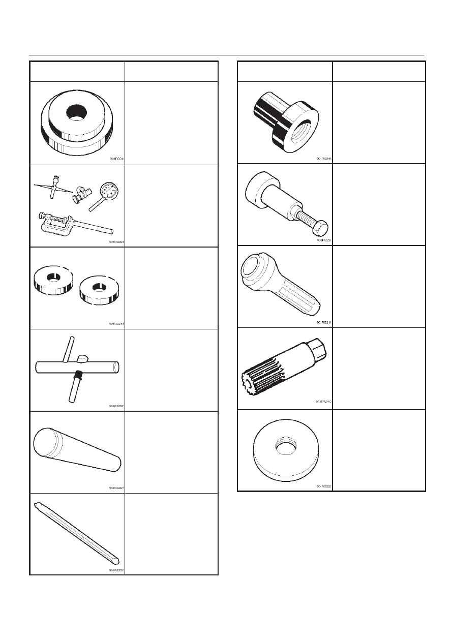
ILLUSTRATION

TOOL NO.

TOOL NAME

5–8840–2166–0

(J–23597–7)

Gauge plate

5–8840–0126–0

(J–8001)

Dial indicator

5–8840–2167–0

(J–23597–8)

Disc

5–8840–0128–0

(J–23597–1)

Arbor

9–8522–1165–0

(J–6133–01)

Installer; Pinion bearing

5–8840–2293–0

(J–39209)

Punch; End nut lock

ILLUSTRATION

TOOL NO.

TOOL NAME

5–8840–2162–0

(J–24244)

Installer; Side bearing

5–8840–2323–0

(J–39602)

Remover; Outer bearing

5–8840–2165–0

(J–37263)

Installer; Pinion oil seal

5–8840–2682–0

(J–44450)

Holder; Side gear

5–8840–0129–0

(J–23597–12)

Rear pilot

DIFFERENTIAL (REAR 244mm)

4A2B–1

DRIVELINE/AXLE

DIFFERENTIAL (REAR 244mm)

CONTENTS

Service Precaution

4A2B–1

. . . . . . . . . . . . . . . . . . . . . . 

General Description

4A2B–3

. . . . . . . . . . . . . . . . . . . . . 

Diagnosis

4A2B–4

. . . . . . . . . . . . . . . . . . . . . . . . . . . . . . 

Axle Housing

4A2B–5

. . . . . . . . . . . . . . . . . . . . . . . . . . . 

Axle Housing and Associated Parts

4A2B–5

. . . . . . 

Removal

4A2B–5

. . . . . . . . . . . . . . . . . . . . . . . . . . . . . 

Oil Seal Replacement

4A2B–6

. . . . . . . . . . . . . . . . . . 

Installation

4A2B–6

. . . . . . . . . . . . . . . . . . . . . . . . . . . . 

Axle Shaft

4A2B–7

. . . . . . . . . . . . . . . . . . . . . . . . . . . . . . 

Axle Shaft and Associated Parts

4A2B–7

. . . . . . . . . 

Removal

4A2B–7

. . . . . . . . . . . . . . . . . . . . . . . . . . . . . 

Inspection and Repair

4A2B–8

. . . . . . . . . . . . . . . . . . 

Oil Seal Replacement

4A2B–9

. . . . . . . . . . . . . . . . . . 

Installation

4A2B–9

. . . . . . . . . . . . . . . . . . . . . . . . . . . . 

Pinion Oil Seal

4A2B–10

. . . . . . . . . . . . . . . . . . . . . . . . . . 

Pinion Oil Seal and Associated Parts

4A2B–10

. . . . . 

Removal

4A2B–10

. . . . . . . . . . . . . . . . . . . . . . . . . . . . . 

Inspection and Repair

4A2B–11

. . . . . . . . . . . . . . . . . . 

Installation

4A2B–11

. . . . . . . . . . . . . . . . . . . . . . . . . . . . 

Differential Assembly

4A2B–12

. . . . . . . . . . . . . . . . . . . . 

Differential Assembly and Associated Parts 4A2B–12
Removal

4A2B–12

. . . . . . . . . . . . . . . . . . . . . . . . . . . . . 

Installation

4A2B–13

. . . . . . . . . . . . . . . . . . . . . . . . . . . . 

Disassembled View

4A2B–14

. . . . . . . . . . . . . . . . . . . . 

Disassembly

4A2B–15

. . . . . . . . . . . . . . . . . . . . . . . . . . 

Reassembly

4A2B–17

. . . . . . . . . . . . . . . . . . . . . . . . . . 

Differential Cage Assembly

4A2B–24

. . . . . . . . . . . . . . . 

Disassembled View

4A2B–24

. . . . . . . . . . . . . . . . . . . . 

Disassembly

4A2B–25

. . . . . . . . . . . . . . . . . . . . . . . . . . 

Inspection and Repair

4A2B–25

. . . . . . . . . . . . . . . . . . 

Reassembly

4A2B–26

. . . . . . . . . . . . . . . . . . . . . . . . . . 

Limited Slip Differential

4A2B–28

. . . . . . . . . . . . . . . . . . . 

Disassembled View

4A2B–28

. . . . . . . . . . . . . . . . . . . . 

Disassembly

4A2B–29

. . . . . . . . . . . . . . . . . . . . . . . . . . 

Inspection and Repair

4A2B–29

. . . . . . . . . . . . . . . . . . 

Reassembly

4A2B–31

. . . . . . . . . . . . . . . . . . . . . . . . . . 

Main Data and Specifications

4A2B–35

. . . . . . . . . . . . . 

Special Tools

4A2B–37

. . . . . . . . . . . . . . . . . . . . . . . . . . . 

Service Precaution

WARNING: IF SO EQUIPPED WITH A
SUPPLEMENTAL RESTRAINT SYSTEM (SRS),
REFER TO THE SRS COMPONENT AND WIRING
LOCATION VIEW IN ORDER TO DETERMINE
WHETHER YOU ARE PERFORMING SERVICE ON OR
NEAR THE SRS COMPONENTS OR THE SRS
WIRING. WHEN YOU ARE REFORMING SERVICE ON
OR NEAR THE SRS COMPONENTS OR THE SRS
WIRING, REFER TO THE SRS SERVICE
INFORMATION. FAILURE TO FOLLOW WARNINGS
COULD RESULT IN POSSIBLE AIR BAG
DEPLOYMENT, PERSONAL INJURY, OR
OTHERWISE UNNEEDED SRS SYSTEM REPAIRS.

CAUTION: Always use the correct fastener in the
proper location. When you replace a fastener, use
ONLY the exact part number for that application.
ISUZU will call out those fasteners that require a
replacement after removal. ISUZU will also call out
the fasteners that require thread lockers or thread
sealant. UNLESS OTHERWISE SPECIFIED , do not
use supplemental coatings (Paints, greases, or other
corrosion inhibitors) on threaded fasteners or
fastener joint interfaces. Generally,such coatings
adversely affect the fastener torque and the joint
clamping force, and may damage the fastener.  When
you install fasteners, use the correct tightening
sequence and specification.  Following these
instructions can help you avoid damage to parts and
systems.
The 

f

244 differential has two N types A-type and B-

type.
A-type: the sticker with bar code is attached.
B-type: the sticker with no bar code on the lower part
of carrier is attached.

SECTION

4A2B–2

DIFFERENTIAL (REAR 244mm)

In case of Work Shop Manual;

A-type: Refer to ’98 UBS Work Shop Manual.
B-type: Described in ’00UBS Work Shop Manual.

425RY00018

DIFFERENTIAL (REAR 244mm)

4A2B–3

General Description

The rear axle assembly is of the semi–floating type in
which the vehicle weight is carried on the axle housing .
The center line  of the pinion gear is below the center line
of the ring gear (hypoid drive).
All parts necessary to transmit power from the propeller
shaft to the rear wheels are enclosed in a banjo type axle
housing.
The 9.61 inch ring gear rear axle uses a conventional ring
and pinion gear set to transmit the driving force of the
engine to the rear wheels. This gear set transfers this

driving force at a 90 degree angle from the propeller shaft
to the drive shafts.
The axle shafts are supported at the wheel end of the
shaft by a roller bearing.
The pinion gear is supported by two tapered roller
bearings. The pinion depth is set by a shim pack located
between the gear end of the pinion and the roller bearing
that is pressed onto the pinion.  The pinion bearing
preload is set by crushing a collapsible spacer between
the bearings in the axle housing.

420RY00006

The ring gear is bolted onto the differential cage with 12
bolts.
The differential cage is supported in the axle housing by
two tapered roller bearings. The differential and ring gear
are located in relationship to the pinion by using selective
shims and spacers between the bearing and the axle
housing. To move the ring gear, shims are deleted from
one side and an equal amount are added to the other side.
These shims are also used to preload the bearings which

are pressed onto the differential cage. Two bearing caps
are used to hold the differential into the rear axle housing.
The differential is used to allow the wheels to turn at
different rates of speed while the rear axle continues to
transmit the driving force.  This prevents tire scuffing
when going around corners and prevents premature wear
on internal axle parts.
The rear axle is sealed with a pinion seal, a seal at each
axle shaft end, and by a liquid gasket between the
differential carrier and the axle housing.


Content   ..  994  995  996  997   ..