Opel Frontera UBS. Manual - part 947


  Index      Opel     Opel Frontera UBS - service repair manual 1998-2002 year


Search            


Content   ..  945  946  947  948   ..


Opel Frontera UBS. Manual - part 947


6.

Tighten the lock nut to the specified torque.

Lock Nut Torque

N·m (kg·m/lb·ft)

23 (2.3 / 17)

2A – 6 FRONT END ALIGNMENT

4.

Similarly adjust the inside wheel angle of the other
side with stopper bolt.

Maximum Steering Angle

Inside wheel

34°

+0°

-2°

Outside wheel

32°

NOTE:
Maximum steering angles should be set after adjusting
front wheel alignment.
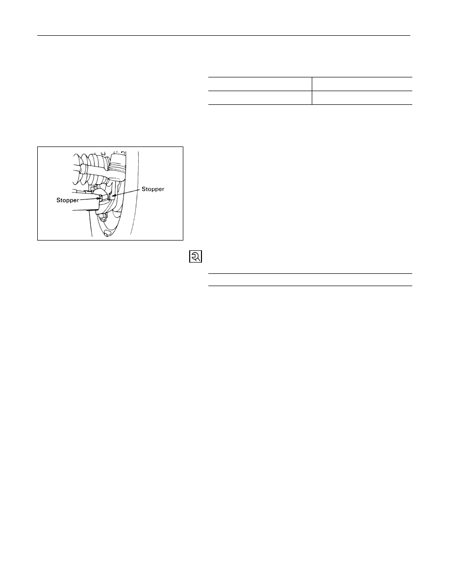
5.

If the stop between the lower link end and the knuckle
comes ahead of the stopper bolt, adjust the stopper
bolt so that inner stopper bolt touches the drop arm
(relay lever).

POWER STEERING  2A – 7

SECTION 2A

POWER STEERING

CONTENTS

PAGE

General Description ......................................................................................................... 2A – 8

Power Steering Gear ................................................................................................... 2A –  9

Hydraulic Pump ........................................................................................................... 2A –  9

Pressure Switch (6VD1, 6VE1 Engine)....................................................................... 2A –  9

Power Steering System Test .......................................................................................... 2A – 10

On-Vehicle Service........................................................................................................... 2A – 12

Bleeding The Power Steering System....................................................................... 2A – 12

Flushing The Power Steering System ....................................................................... 2A – 12

Steering Gear ............................................................................................................... 2A – 13

Power Steering Pump (6VD1, 6VE1 Engine Models) ............................................... 2A – 16

Power Steering Pump (4JG2 Engine Model) ............................................................ 2A – 18

Power Steering Pump (4JX1 Engine Model)............................................................. 2A – 20

Unit Repair........................................................................................................................ 2A – 22

Steering Gear ............................................................................................................... 2A – 22

Power Steering Pump (6VD1, 6VE1 Engine Models) ............................................... 2A – 28

Power Steering Pump (4JG2 Engine Model) ............................................................ 2A – 32

Power Steering Pump (4JX1 Engine Model)............................................................. 2A – 36

2A – 8 POWER STEERING

GENERAL DESCRIPTION

6VD1, 6VE1 Engine Models

4JG2 Engine Model

4JX1 Engine Model

This illustration is based on the LHD model.

POWER STEERING  2A – 9

The hydraulic power steering system consists of a
pump, an oil reservoir, a steering gear, a pressure
hose and a return hose.

POWER STEERING GEAR

The power steering gear has a recirculating ball
system which acts as a rolling thread between the
worm shaft and the rack piston. When the worm
shaft is turned right, the rack piston moves up in
gear. Turning the worm shaft left moves the rack
piston down in gear. The rack piston teeth mesh
with the sector, which is part of the sector shaft.
Turning the worm shaft turns the sector shaft,
which turns the wheels through the steering
linkage.
The control valve in the steering gear directs the
power steering fluid to either side of the rack
piston. The rack piston converts the hydraulic
pressure into a mechanical force. If the steering
system becomes damaged and loses hydraulic
pressure, the vehicle can be controlled manually.

HYDRAULIC PUMP

The hydraulic pump is vane-type design.
There are two bore openings at the rear of the
pump housing. The smaller opening contains the
pressure line union and flow control valve.

PRESSURE SWITCH (6VD1,
6VE1 Engine)

When hydraulic pressure reaches 3650 ± 350 kPa
(530 ± 50 PSI), the pressure switch closes causing
ECM to actuate the idle air control valve to prevent
the overload-induced engine speed down. The
switch opens when hydraulic pressure drops to
3150 ± 350 kPa (460 ± 50PSI).


Content   ..  945  946  947  948   ..