Opel Frontera UBS. Manual - part 937


  Index      Opel     Opel Frontera UBS - service repair manual 1998-2002 year


Search            


Content   ..  935  936  937  938   ..


Opel Frontera UBS. Manual - part 937


1D – 12 COMPRESSOR OVERHAUL

6. Loosen three screws and remove the field coil.

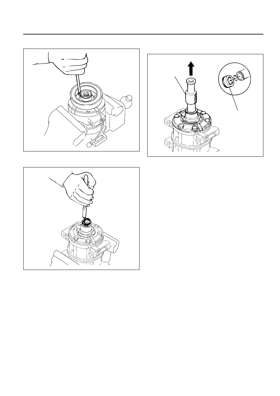
7. Remove snap ring by using snap ring pliers.

8. Remove shaft seal assembly (2) by using shaft seal

remover J-33942 (1).

Engage the remover hook with the shaft seal
assembly groove and slowly draw the shaft seal
assembly out.

NOTE
The shaft seal is precision-machined and its
critical parts are finished to extremely close
tolerances. The assembly must be handled
with great care, it slips face demanding
particularly careful handling.
The shaft seal can not be reused. Install a new
shaft seal at reassembly.
Take care not to scratch or otherwise damage
the shaft seal face.
Keep the shaft seal free from lint and dirt.

9. Remove through bolt.

871RY00006

871RY00017

1

2

871RY00018

COMPRESSOR OVERHAUL  1D – 13

10. Remove front cylinder head.

11. Remove o-ring.

Alternately tap the projections on the
circumference of the front cylinder head with a
screwdriver and a plastic hammer to remove the
front cylinder head.

12. Remove gasket.

13. Remove front valve plate.

14. Remove front suction valve.

NOTE
Check the front valve plate for scratching and
bending.
Check the front valve plate and the front
cylinder head for nicks and burrs on the
sealing surface.
Buff or replace the valve plate and cylinder
head if nicks and burrs are present.
Check that the front valve plate passage is free
from obstructions.
Check the front valve plate and the cylinder
head for cracks.
Replace the valve plate and cylinder head if
cracks are present.

15. Remove rear cylinder head.

16. Remove o-ring.

Alternately tap the projections on the
circumference of the rear cylinder head with a
screwdriver and a plastic hammer to remove the
rear cylinder head.

17. Remove gasket.

18. Remove rear valve plate.

19. Remove rear suction valve.

20. Remove cylinder and shaft assembly.

NOTE
Check the rear valve plate for scratching and
bending.
Check the rear valve plate and the rear
cylinder head for nicks and burrs on the
sealing surface.
Buff or replace the valve plate and cylinder
head if nicks and burrs are present.
Check that the rear valve plate passage is free
from obstructions.
Check the rear valve plate and the cylinder
head for cracks.
Replace the valve plate and cylinder head if
cracks are present.

871RY00019

871RY00020

1D – 14 COMPRESSOR OVERHAUL

Installation

1. Install cylinder and shaft assembly.

Clamp the cylinder shaft assembly in a vise.
The rear side of the cylinder shaft assembly must
be facing up.

2. Install rear suction valve.

Apply a coat of new compressor oil to the new
suction valve (2).
Install the suction valve by aligning it with the
spring pin and the cylinder valve relief grooves.

Legend

(1)

Escape Groove

(2)

Suction Valve

(3)

Piston

3. Install rear valve plate.

Apply a coat of new compressor oil to the new
valve plate.
Install the valve plate to the suction valve by
aligning it with the spring pin.

NOTE
Do not mix up the front and rear valve plate.

4. Install gasket.

Apply a coat of new compressor oil to the new
gasket.
Install the gasket (3) to the valve plate (4).

5. Install o-ring (2).

6. Install rear cylinder head (1).

Apply a coat of new compressor oil to the new o-
ring (2).
Install the o-ring (2) to the rear cylinder head (1).
Install the rear cylinder head.
Top the rear cylinder head (1) into place with a
plastic hammer.

7. Install front suction valve.

Set the cylinder shaft assembly with the front side
facing up.
Apply a coat of new compressor oil to the new
suction valve (2).
Install the suction valve (2) by aligning it with the
spring pin and the cylinder valve relief grooves.

Legend

(1)

Escape Groove

(2)

Suction Valve

(3)

Piston

1

2

3

871RY00021

5

4

3

2

1

871RY00022

1

2

3

871RY00021

COMPRESSOR OVERHAUL  1D – 15

8. Install front valve plate.

Apply a coat of new compressor oil to the new
valve plate.
Install the valve plate to the suction valve by
aligning it with the spring pin.

NOTE
Do not mix up the front and rear valve plates.

9. Install gasket

Apply new compressor oil to the new gasket.

Install the gasket to the valve plate by a aligning it
with the spring pin.

10. Install o-ring.

11. Install front cylinder head.

Apply a coat of new compressor oil to the new O-
ring.
Install the O-ring to the front cylinder head.
Install the front cylinder head.
Tap the front cylinder head into place with a
plastic hammer.

NOTE
When installing the cylinder head, be careful
that the end of the drive shaft does not
damage the shaft seal assembly surface in the
cylinder head.

12. Install through bolt.

Gaskets cannot reused. Always replace new
ones. Tighten the bolts to the specified torque a
little at a time in the sequence shown in the
illustration.

Torque: 22N·m (16 lb·ft)

NOTE
Rotate the compressor drive shaft two or three
times to make sure that it moves smoothly.

1

4

5

2

3

6

871RY00016

871RY00023


Content   ..  935  936  937  938   ..