Opel Frontera UBS. Manual - part 930


  Index      Opel     Opel Frontera UBS - service repair manual 1998-2002 year


Search            


Content   ..  928  929  930  931   ..


Opel Frontera UBS. Manual - part 930


1B–114 AIR CONDITIONING

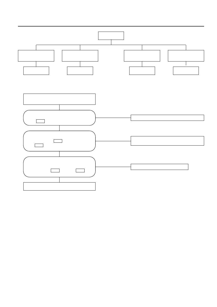
Chart A: Fan Does Not Rotate At All

NO

Failure on the power supply system.

NO

Failure on the ground or the harness is

disconnected.

NO

Replace the fan motor.

YES

YES

YES

Turn on the ignition switch (the engine is

started).

Refer to Charts B and C.

Is the battery voltage present between the
chassis harness side connector terminal
No.2 

and the ground?

B-5

Are the chassis harness side connector
terminals No.4 

and the ground

(No. ) 

conducted?

B-1

I-51

Is the battery voltage present between
the chassis harness side connector
terminals No.1 

and No.2 

?

B-5

B-5

Type of trouble

The fan does not

rotate in any mode

other than MAX HI.

The fan does not stop.

Chart B

Chart C

Chart D

The fan does not

rotate in the MAX HI

mode.

The fan does not

rotate at all.

Chart A

AIR CONDITIONING  1B–115

Chart B: Fan Does Not Rotate in MAX HI Mode

NO

The harness is disconnected.

YES

NO

NO

NO

YES

YES

YES

Turn on the ignition switch (the engine is

started).

Set the fan switch to the MAX HI.

The harness is

disconnected.

Failure on the automatic

heater/air conditioner

control unit.

Failure on the MAX

HI relay.

Failure on the
ground or the

harness is

disconnected.

Is the battery voltage present between the
chassis harness side connector terminal
No.12 

and the ground?

I-32

Are the chassis harness side connector
terminal No.4

and the body ground

(No. ) 

conducted?

B-1

I-51

Are the chassis harness side connector
terminals No.1 

and No.2 

conducted?

I-51

B-5

Is the battery voltage present between
the chassis harness side connector
terminal No.1

and No.3 

?

I-51

I-51

1B–116 AIR CONDITIONING

Chart C: Fan Does Not Rotate In Any Mode Other Than MAX HI

NO

Replace the power transistor.

NO

Failure on the ground or the harness is

disconnected.

NO

The harness is disconnected.

NO

The harness is disconnected.

YES

YES

YES

YES

Failure on the automatic heater/air

conditioner control unit.

Is the power transistor performance
normal? (Refer to the later section on
"Check Up".)

Is the battery voltage present between
the chassis harness side connector
terminal No.3 

and the ground No.

?

B-1

I-50

Is conduction provided between the
following chassis harness side connector
terminals?
No.1 and 

No.1 .

No.1 and 

No.17 .

I-33

B-5

I-50

B-5

Are the chassis harness side connector
terminals No.2 

and No.19 

conducted?

I-33

I-50

AIR CONDITIONING  1B–117

Chart D: Fan Does Not Stop

NO

Replace the power transistor.

NO

Replace the relay.

YES

NO

YES

Turn on the ignition switch (the engine is

started).

YES

Is the power transistor performance
normal? (Refer to the later section on
"Check Up".)

Is the MAX HI relay performance
normal? (Refer to the later section on
"Check Up".)

Is the battery voltage present between
the chassis harness side connector
terminals No.1 

and No.3 

?

I-51

I-51

The chassis harness side connector
terminals No.1 

and No.2 

, or

No.1 

and No.1 

is short

circuited.

I-50

B-5

I-51

B-5

Failure on the automatic heater/air
conditioner control unit. Or, the harness
line is short circuited between the chassis
harness side connector terminals No.3

and No.12 

.

I-32

I-51


Content   ..  928  929  930  931   ..