Opel Frontera UBS. Manual - part 912


  Index      Opel     Opel Frontera UBS - service repair manual 1998-2002 year


Search            


Content   ..  910  911  912  913   ..


Opel Frontera UBS. Manual - part 912


1B – 42 AIR CONDITIONING
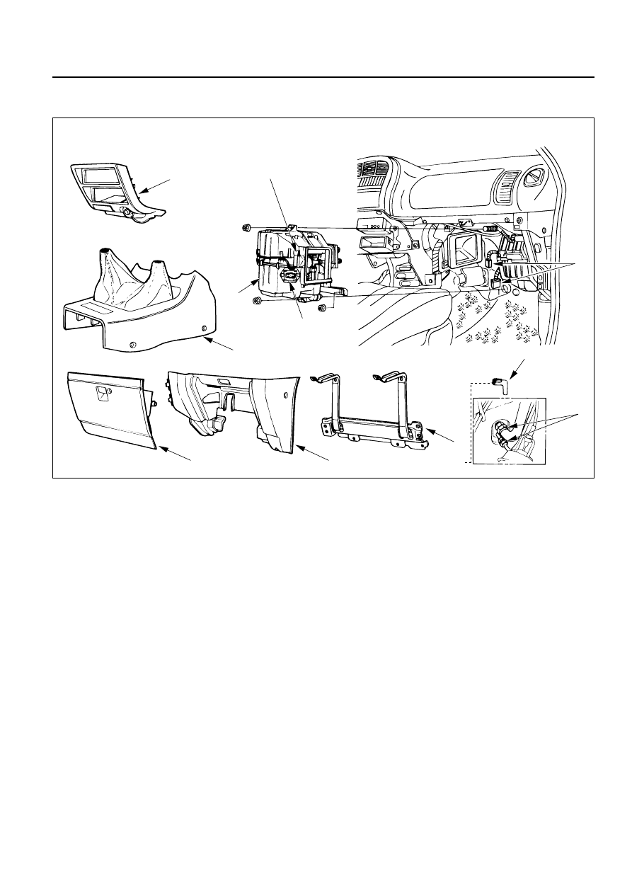
Removal Steps

1. Front console assembly
2. Lower cluster assembly
3. Glove box
4. Instrument panel passenger

lower cover assembly

5. Passenger knee bolster

reinforcement assembly

6. Resistor and electronic

thermostat connector

7. Drain hose
8. Refrigerant line
9. Evaporator assembly

Installation Steps

To install, follow the removal steps in the
reverse order.

EVAPORATOR ASSEMBLY

1

2

3

4

5

6

7

8

9

This illustration is based on LHD

Electronic thermostat

Resistor

850RW00001

AIR CONDITIONING  1B – 43

REMOVAL

Preparation:

Disconnect the battery ground cable

Discharge and recover refrigerant (Refer to
“REFRIGERANT RECOVERY” in this section.) 

1. Front Console Assembly 

2. Lower Cluster Assembly 

3. Glove Box 

4. Instrument Panel Passenger Lower Cover Assembly

5. Passenger Knee Bolster Reinforcement Assembly

Refer to Section 10 “BODY” for INSTRUMENT
PANEL ASSEMBLY removal procedure.

6. Resistor and Electronic Thermostat Connector

7. Drain Hose

8. Refrigerant Line

Use a back-up wrench when disconnecting and
reconnecting the refrigerant lines.

When removing the refrigerant line connected part,
the connecting part should immediately be
plugged or capped to prevent foreign matter from
being mixed into the line. 

9. Evaporator Assembly

INSTALLATION

To install, follow the removal steps in the reverse order,
noting the following points: 

1. To install a new evaporator assembly, add 50cc

(1.4 Imp fl oz) of new compressor oil to a new core.

2. Tighten the refrigerant outlet line to the specified

torque.

Outlet Line Torque

N·m (kg·m / lb·ft)

25 (2.5 / 18)

3. Tighten the refrigerant inlet line to the specified

torque.

Inlet Line Torque

N·m (kg·m / lb·ft)

15 (1.5 / 11)

4. O-rings cannot be reused. Always replace with new

ones.

5. Be sure to apply new compressor oil to the O-rings

when connecting lines.

Electronic thermostat
connector

Resistor connector

1B – 44 AIR CONDITIONING

Legend

(1)

Lining

(2)

Expansion Valve

(3)

O-ring

(4)

Lower Case

(5)

Evaporator Assembly

(6)

Pollen Filter

(7)

Attaching Screw

(8)

Lining

(9)

Evaporator Core

(10)

Electronic Thermostat

(11)

Upper Case

EVAPORATOR CORE AND/OR EXPANSION VALVE

This illustration is based on LHD

8

1

2

3

5

4

6

7

9

11

10

874RY00012

AIR CONDITIONING  1B – 45

Removal

1. Disconnect the battery ground cable.

2. Discharge and recover refrigerant.

Refer to Refrigerant Recovery in this section.

3. Remove evaporator assembly.

Refer to Evaporator Assembly in this section.

4. Remove pollen filter.

5. Pull the sensor from the evaporator assembly.

6. Remove attaching screw.

7. Remove upper case.

8. Remove lower case.

Slit the case parting face with a knife since the
lining is separated when removing the
evaporator.

Lift to remove the upper case.

9. Remove evaporator core.

10. Remove expansion valve.

Tear off the insulator carefully.

Use a back-up wrench when disconnecting all
refrigerant pipes.

Installation

To install, follow the removal steps in the reverse
order, noting the following points:

1. The sensor is installed on the core with the clip.

2. The sensor must not interfere with the

evaporator core.

3. When installing the new evaporator core, install

the thermo sensor (2) to the evaporator core (1)
specified position with the clip in the illustration.

874RS006

874RY00005

874RY00006

SENSOR TO BE LOCATED
AT 7TH LINE FROM LEFT

57.5mm(2.26 in.)

2

1

Lower case

Upper case

874RX021


Content   ..  910  911  912  913   ..