Opel Frontera UBS. Manual - part 893


  Index      Opel     Opel Frontera UBS - service repair manual 1998-2002 year


Search            


Content   ..  891  892  893  894   ..


Opel Frontera UBS. Manual - part 893


0B–10 MAINTENANCE AND LUBRICATION
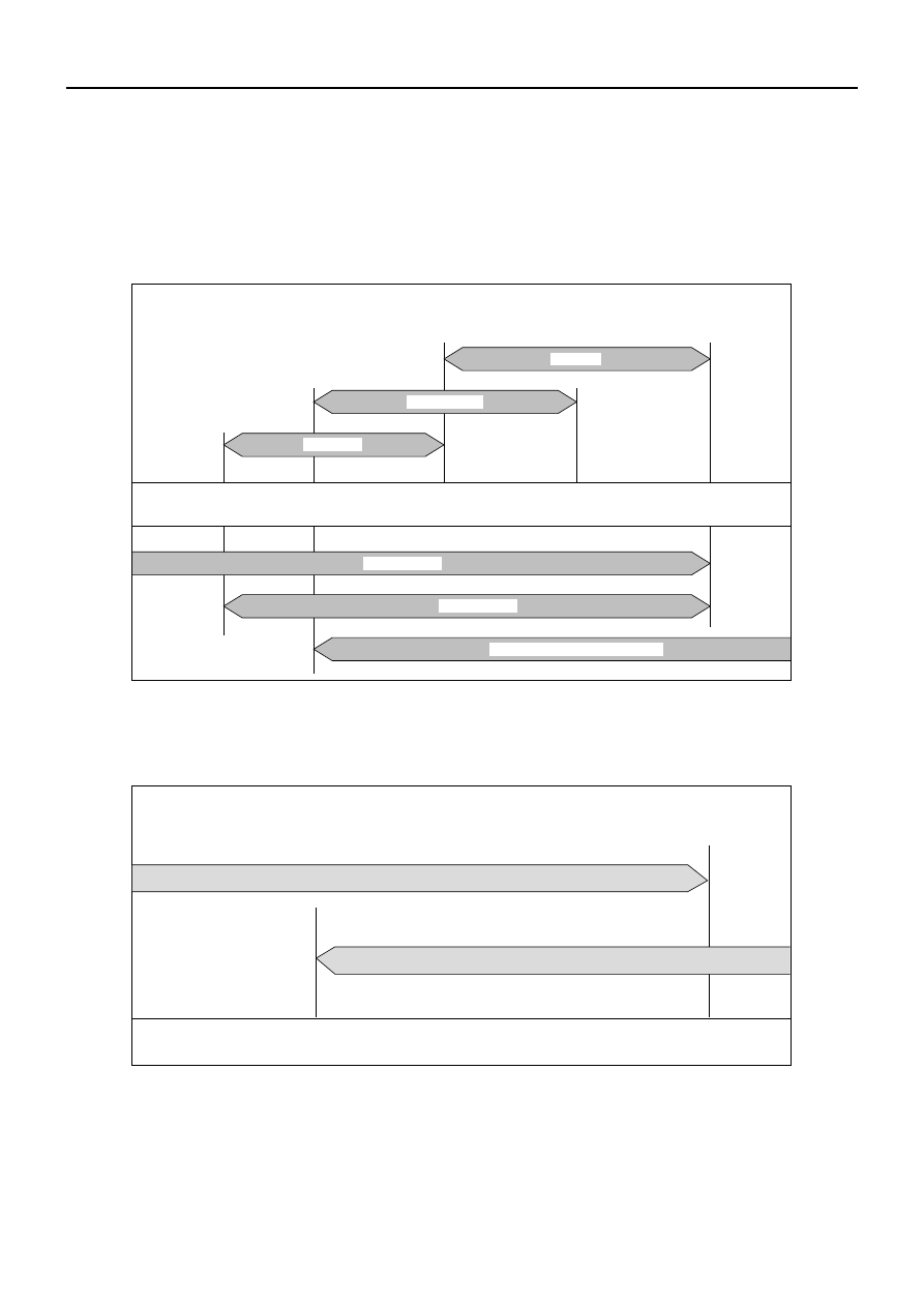
OIL VISCOSITY CHART

Lubricants should be carefully selected according to the lubrication chart. It is also important to select
viscosity of lubricants according to the ambient temperature by referring to the following table.

OIL VISCOSITY CHART FOR GASOLINE ENGINE

APPLY GASOLINE ENGINE OIL 

SAE 30

SAE 5W-30

SAE 15W-40,20W-40,20W-50

SAE 10W-30

SAE 20,20W

SAE 10W

EG-01

(Multi grade)

(Single grade)

VISCOSITY GRADE - AMBIENT TEMPERATURE

−25˚C

−13˚F

−15˚C

5˚F

38˚C

100˚F

15˚C

60˚F

0˚C

32˚F

OIL VISCOSITY CHART FOR DIESEL ENGINE

APPLY DIESEL ENGINE OIL 

VISCOSITY GRADE - AMBIENT TEMPERATURE

(Multi grade )

SAE  5W-30

SAE 10W-30

–25

°

C

–15

°

C

0

°

C

–10

°

C

15

°

C

25

°

C 30

°

C

–13

°

F

5

°

F

32

°

F

14

°

F

60

°

F

77

°

F

86

°

F

905RW017

MAINTENANCE AND LUBRICATION 0B–11

OIL VISCOSITY CHART FOR MANUAL TRANSMISSION AND TRANSFER CASE

APPLY ENGINE OIL 

SAE 5W-30

SAE 15W-40,20W-40,20W-50

SAE 10W-30

SAE 40,50

ET-12

(Multi-grade)

(Single grade)

VISCOSITY GRADE - AMBIENT TEMPERATURE

SAE 30

−25˚C

−13˚F

−10˚C

14˚F

35˚C

95˚F

20˚C

68˚F

5˚C

41˚F

10˚C

50˚F

OIL VISCOSITY CHART FOR FRONT AXLE (Manual and Auto locking hub model) 

AND REAR AXLE

APPLY GEAR OIL 

SAE 75W-90

SAE 80W-140

SAE 80W-90

GA-06

(Multi grade)

(Single grade)

GEAR  OIL  VISCOSITY  GRADE - AMBIENT  TEMPERATURE

−25˚C

−13˚F

30˚C

86˚F

−10˚C

14˚F

35˚C

95˚F

15˚C

59˚F

0˚C

32˚F

SAE 80W

SAE 75W

SAE 140

SAE 90

0B–12 MAINTENANCE AND LUBRICATION

OIL VISCOSITY CHART FOR FRONT AXLE (Shift on the fly model) 

APPLY GEAR OIL 

GEAR OIL VISCOSITY GRADE – AMBIENT TEMPERATURE

(Multi grade)

SAE 80W – 90, 80W – 140

SAE 75W – 90

–25

°

C

–13

°

F

14

°

F

32

°

F

59

°

F

86

°

F

95

°

F

–10

°

C

15

°

C

30

°

C

35

°

C

0

°

C

CAUTION

When fasteners are removed, always
reinstall them at the same location from
which they were removed.  If a fastener
needs to be replaced, use the correct part
number fastener for that application.  If the
correct part number fastener is not available,
a fastener of equal size and strength (or
stronger) may be used. 

Fasteners that are not reused, and those
requiring thread locking compound, will be
called out.  The correct torque values must
be used when installing fasteners that
require it.  If the above conditions are not
followed, parts or system damage could
result.

HEATING AND VENTILATION  1A – 1

SECTION 1A

HEATING AND VENTILATION

CONTENTS

PAGE 

General Description . . . . . . . . . . . . . . . . . . . . . . . . . . . . . . . . . . . . . . . . . . . . . . . . . . . . . 1A– 2

Heater. . . . . . . . . . . . . . . . . . . . . . . . . . . . . . . . . . . . . . . . . . . . . . . . . . . . . . . . . . . . . . . 1A– 2

Control Lever Assembly . . . . . . . . . . . . . . . . . . . . . . . . . . . . . . . . . . . . . . . . . . . . . . . . 1A– 3

Ventilation . . . . . . . . . . . . . . . . . . . . . . . . . . . . . . . . . . . . . . . . . . . . . . . . . . . . . . . . . . . 1A– 3

Air Select Knob . . . . . . . . . . . . . . . . . . . . . . . . . . . . . . . . . . . . . . . . . . . . . . . . . . . . . . . 1A– 4

Air Source Select Lever . . . . . . . . . . . . . . . . . . . . . . . . . . . . . . . . . . . . . . . . . . . . . . . . 1A– 4

Fan Control Knob . . . . . . . . . . . . . . . . . . . . . . . . . . . . . . . . . . . . . . . . . . . . . . . . . . . . . 1A– 4

Temperature Control Knob . . . . . . . . . . . . . . . . . . . . . . . . . . . . . . . . . . . . . . . . . . . . . 1A– 4

Ceramic Heater . . . . . . . . . . . . . . . . . . . . . . . . . . . . . . . . . . . . . . . . . . . . . . . . . . . . . . . 1A– 5

On-Vehicle Service . . . . . . . . . . . . . . . . . . . . . . . . . . . . . . . . . . . . . . . . . . . . . . . . . . . . . . 1A– 6

Heater Unit . . . . . . . . . . . . . . . . . . . . . . . . . . . . . . . . . . . . . . . . . . . . . . . . . . . . . . . . . . 1A– 6

Heater Core and/or Mode Door . . . . . . . . . . . . . . . . . . . . . . . . . . . . . . . . . . . . . . . . . . 1A– 8

Heater Mode Control Link Unit . . . . . . . . . . . . . . . . . . . . . . . . . . . . . . . . . . . . . . . . . . 1A–10

Heater Temperature Control Link Unit . . . . . . . . . . . . . . . . . . . . . . . . . . . . . . . . . . . . 1A–12

Blower Assembly . . . . . . . . . . . . . . . . . . . . . . . . . . . . . . . . . . . . . . . . . . . . . . . . . . . . . 1A–14

Blower Link Unit and/or Mode Door. . . . . . . . . . . . . . . . . . . . . . . . . . . . . . . . . . . . . . 1A–16

Blower Motor . . . . . . . . . . . . . . . . . . . . . . . . . . . . . . . . . . . . . . . . . . . . . . . . . . . . . . . . 1A–18

Rear Heater Duct, Defroster Nozzle and Ventilation Duct . . . . . . . . . . . . . . . . . . . . 1A–20

Center and/or Side Vent . . . . . . . . . . . . . . . . . . . . . . . . . . . . . . . . . . . . . . . . . . . . . . . 1A–22

Control Lever Assembly and/or Control Cables . . . . . . . . . . . . . . . . . . . . . . . . . . . . 1A–24

Control Panel Illumination Bulb. . . . . . . . . . . . . . . . . . . . . . . . . . . . . . . . . . . . . . . . . . 1A–27

Resistor . . . . . . . . . . . . . . . . . . . . . . . . . . . . . . . . . . . . . . . . . . . . . . . . . . . . . . . . . . . . . 1A–28

Ceramic Heater and/or Full Hot Switch . . . . . . . . . . . . . . . . . . . . . . . . . . . . . . . . . . . 1A–30

SECTION


Content   ..  891  892  893  894   ..