Opel Frontera UBS. Manual - part 888


  Index      Opel     Opel Frontera UBS - service repair manual 1998-2002 year


Search            


Content   ..  886  887  888  889   ..


Opel Frontera UBS. Manual - part 888


GENERAL INFORMATION 0A–3

HOW TO USE THIS MANUAL

1. Find the applicable section by referring to the

table of contents on the introduction page of
each manual.

2.

In “Service Information”, an opening section of
each manual, the troubleshooting, maintenance
servicing, service data and/or information on
special tools required for the service operations
described in the next subsequent sections are
arranged and compiled so concisely that you
can see at a first glance.

3. Each section except the Service Information

section is basically arranged in the following
order of headings:

General description
On-vehicle service
Unit repair

4. The service operations are in two groups: one is

the “On-vehicle service” where operations can
be directly performed on the vehicle, and the
other is the “Unit repair” where the operations
are done on the work bench after removing the
unit from the vehicle.

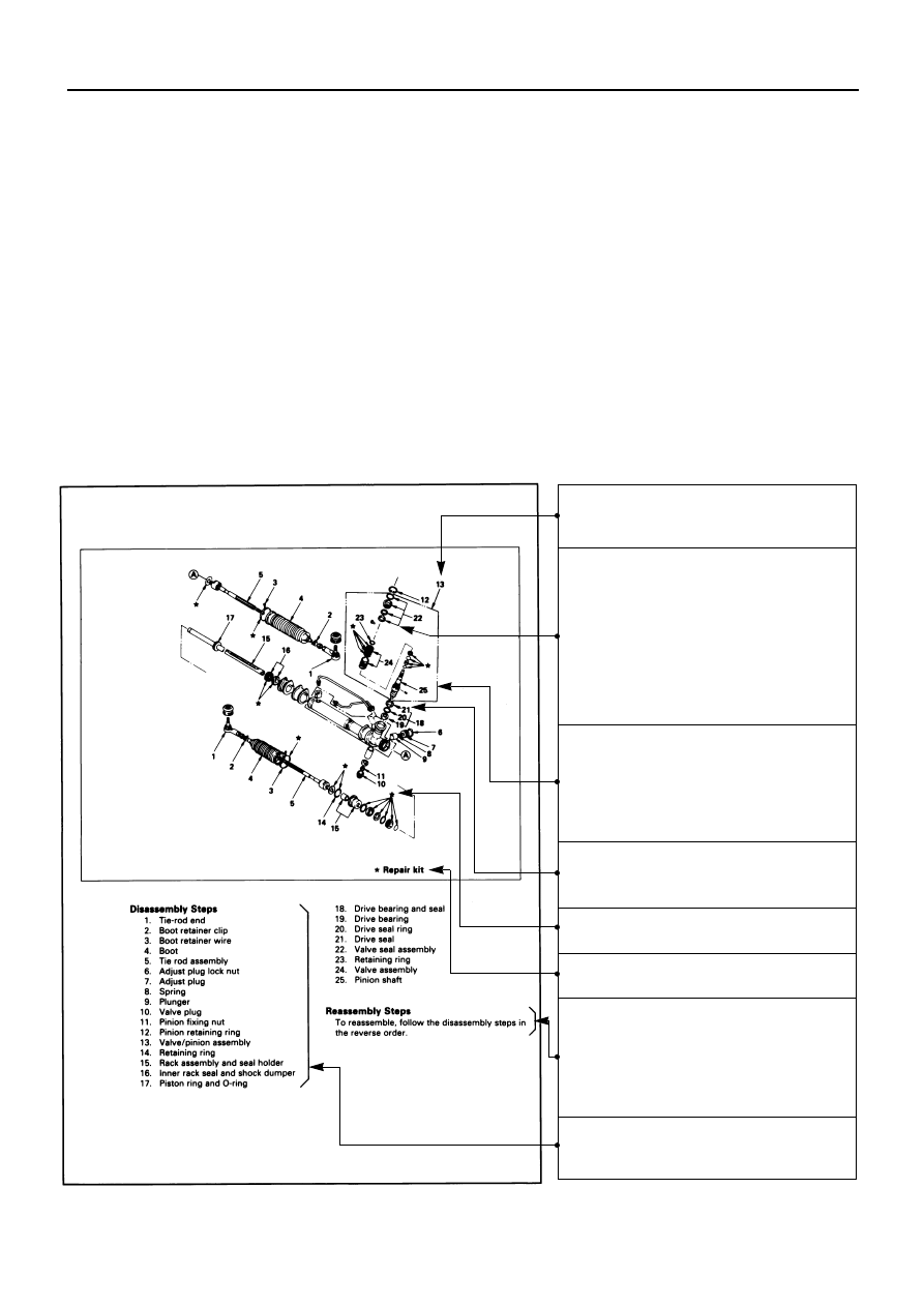
5. Each service operation section begins with a

disassembled view of unit or equipment, which
is useful to find relative components, service
procedure, availability and contents of repair
kits, etc.

The number represents sequence of
removal or disassembly

Removal of unnumbered the parts
(excluding bolts, nuts, washers,
gaskets, cotter pins, etc.) is
unnecessary unless replacement is
needed.
Where parts replacement requires
specific information, instructions are
given in “Inspection and Repair”.

This frame is to be removed as a
large disassembly with all the parts
assembled in the frame. Each one of
the parts in the frame is removed as
a small disassembly.

Parts to be removed or installed as a
unit.

★  Parts contained in repair kit.

★  Indicates repair kit availability.

When the installation (reassembly)
procedure is the reverse order of the
removal (disassembly) procedure,
the sequence of service operation
and the parts names will be omitted.

Name of parts listed in sequence of
service operation. 

For illustrations where there are few items to
be performed:

The sequence of removal
(disassembly) and the parts names
will be given.

The symbol mark attached to the title
indicates the action to be taken in the
operations of each title.
Example for this case;

1st step – Reassemble pinion shaft

The numbers given to the installation
(assembly) procedure are the same
as those given in the removal
(disassembly) procedure in the
illustration. Therefore, start with the
larger number during reassembly.

The titles of operations done in the
illustration are given in bold letters.
They are described in the order of
the procedure of the operations.

Special tools are identified with tool
name and/or tool number.
The drawing illustrates how the tool
is used.

Service data and specifications are
listed in table.

Important note.

The action symbol indicates the step
of service to be followed.
Refer to the following paragraph for
the meaning of each symbol.

information such as the notes in each operation,
and places where special tools are to be used
and their usage, and the specified service data.

0A–4 GENERAL INFORMATION

6. After the illustration, the details of each

operation are shown in the order the operations
are carried out in the illustration. Refer to the
explanations when checking important

GENERAL INFORMATION 0A–5

7. In this manual, the following action symbols

are used to indicate the type of service
operations to be performed.

. . .

Remove or disconnect

. . .

Adjust

. . .

Install or connect

. . .

Clean

. . .

Disassemble

. . .

Pay close attention - Important

. . .

Reassemble

. . .

Tighten to specified torque

. . .

Align the marks

. . .

Use special tool(s)

. . .

Correct direction

. . .

Lubricate with oil

. . .

Inspect

. . .

Lubricate with grease

. . .

Take measurement

. . .

Use liquid gasket

8. The service standard is indicated in terms of

“Standard” and “Limit”.
The “Standard” means the assembly standard
and standard range within which the parts are

considered serviceable.
“Limit” indicates the limit value (Correction or
replacement is necessary when measurement
is beyond this limit.)

VEHICLE IDENTIFICATION NUMBER (VIN)

This is the legal identification of the vehicle.
It appears on the manufacturer’s Plate attached to the left
of the engine compartment front end. VIN number is also
stamped on the rear right side of the frame.

VIN

VIN

ISUZU MOTORS LTD.

JAC

UBS

25

G

Y

7

200001

Sequential Number

Plant Code

Model Year (Y: 2000)

Wheel Base (D: Short, G: Long)

Engine Type (25: 6VD1, 26: 6VE1, 69: 4JG2, 73: 4JX1)

Vehicle Model

World Manufacturer Identifier

ENGINE SERIAL NUMBER

The engine serial number is stamped on the left rear lower
area of the cylinder block above the starter.

4JG2

0A–6 GENERAL INFORMATION

IDENTIFICATION

905RY00014

4JX1

905RW014


Content   ..  886  887  888  889   ..