Opel Frontera UBS. Manual - part 806


  Index      Opel     Opel Frontera UBS - service repair manual 1998-2002 year


Search            


Content   ..  804  805  806  807   ..


Opel Frontera UBS. Manual - part 806


8F–52

BODY STRUCTURE

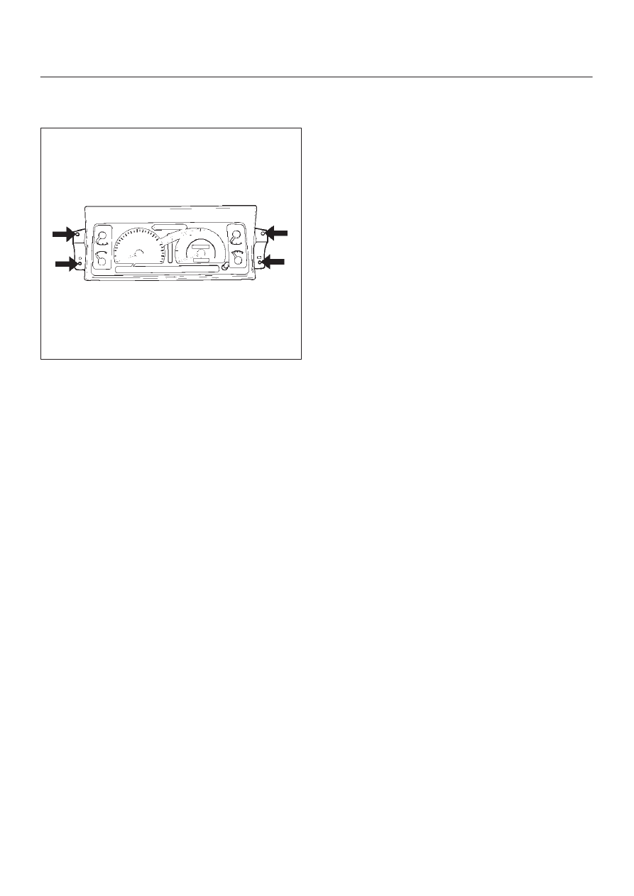
13. Remove meter assembly.

D

Remove the 4 meter assembly fixing screws and
disconnect the meter harness connectors. 

821RS034

14. Remove control lever assembly.

D

Refer to HVAC System in HVAC section.

15. Remove radio assembly.

D

Remove 2 fixing screws.

16. Remove vent duct assembly.

D

Remove 5 fixing screws.

17. Remove instrument harness assembly.

D

Remove the 4 fixing screws, fasteners at the 4
positions and the clips at the 7 positions.

18. Remove side defroster grille.

NOTE: For the order of removal steps in which each
items contained in the instrument panel assembly are
removed individually, refer to the chart.

8F–53

BODY STRUCTURE

Installation

To install, follow the removal steps in the reverse order.
Order Of Removal/Installation Steps For Each Item

Removal Item

Removal Procedure

Removal Step

Front console assem-
bly

Shift knob (M/T), Power & Winter SW (A/T), Transfer knob, Seat
heater/Miller SW conn. and 4 screws

1, 2

Lower cluster assem-
bly

3 screws, Ciger lighter conn. and Ashtray illumination conn.

1

3

Glove box

2 screws

4

Instrument panel pas-
senger lower cover

7 screws and 1 clip

1

5

Passenger knee bol-
ster reinforcement

4 nuts and 4 bolts

1

6

Instrument panel driver
lower cover

Engine hood opening fixing screw, 2 screws, 1 bolt, 1 clip and fasten-
ers at 4 positions

1

3, 7

Driver knee bolster

6 nuts

1

3, 7, 8

Front defroster grille

Claws at 8 positions

9

Instrument panel as-
sembly

2 bolts (SRS adjust bracket

 cross beam), A/C control cable (Unit

side at 3 position), Instrument harness connector (Driver side 5 posi-
tion, assist side 3 position), SRS module conn., Radio antenna jack,
Earth cable, 9 bolts and 3 nuts

1

10

Passenger inflator
module

4 nuts (SRS module

Instrument panel), 2 nuts 0 and 2 washers

(SRS module

support bracket) and 2 clips

1

6, 11

Instrument panel clus-
ter

5 Screws, fastener at 4 position and each SW conn.

1

3, 7, 12

Meter assembly

4 screws and connectors

1

3, 7, 12, 13

A/C control panel as-
sembly

4 screws and connectors

1

3, 7, 12, 14

Radio assembly

2 screws

1

3, 15

Vent duct assembly

5 screws

1

10, 16

Instrument harness as-
sembly

4 screws, fasteners at 4 position, and clips at 7 position

1

10, 17

Side defroster grille

18

M/T = Manual Transmission
A/T = Automatic Transmission
SRS = Supplemental Restraint System
A/C = Air Conditioning

8F–54

BODY STRUCTURE

Cross Beam Assembly

Parts Location

This illustration es based on RHD and W/SRS

740RW100

Legend

(1) Instrument Panel Assembly
(2) Cross Beam Assembly
(3) Side Support Bracket Assembly (RH)
(4) Brake Pedal Mounting Bracket Assembly

(5) Steering Support Bracket Assembly
(6) Instrument Panel Center Bracket
(7) Side Support Bracket Assembly (LH)
(8) Steering Column Fixing Bolts
(9) Cross Beam Center Bracket

Removal

1. Disconnect battery ground cable.
2. Remove instrument panel assembly.

D

Refer to Instrument Panel Assembly in this section.

3. Remove side support bracket assembly (LH/RH).

D

Remove the 4 fixing bolts on both sides.

4. Remove cross beam center bracket

D

Remove 2 fixing nuts.

5. Remove instrument panel center bracket.

D

Disconnect the PCM and EBCM connector.

D

Remove the DERM (SRS) with 3 fixing nuts.

CAUTION: For precautions on installation or
removal of SRS — air bag system, refer to
Supplemental Restraint System (SRS) — AIR BAG in
Restraint section.

D

Remove the 2 fixing nuts (upper) and the 4 fixing
bolts (lower).

8F–55

BODY STRUCTURE

740RW101

6. Remove steering column fixing bolts.

D

Remove 2 fixing bolts.

431RW007

7. Remove brake pedal mounting bracket assembly.

D

Disconnect the 2 brake pedal mounting bracket
assembly fixing nuts, and remove the antitheft
controller.

D

Disconnect the brake pedal link and the brake
switch, and remove the 4 fixing bolts and the nuts
on the bracket.

310RW014

8. Remove steering support bracket assembly.

D

Remove the 2 fixing bolts (upper side) (1) and the 3
fixing nuts (lower side) (2). 

740RW102

9. Remove cross beam assembly.

D

Disconnect the harness clips from the crossbeam
assembly, and remove 2 fixing bolts on both sides
and 2 fixing nuts in the center.

Installation

To install, follow the removal steps in the reverse order.


Content   ..  804  805  806  807   ..