Opel Frontera UBS. Manual - part 633


  Index      Opel     Opel Frontera UBS - service repair manual 1998-2002 year


Search            


Content   ..  631  632  633  634   ..


Opel Frontera UBS. Manual - part 633


8A–16

LIGHTING SYSTEM

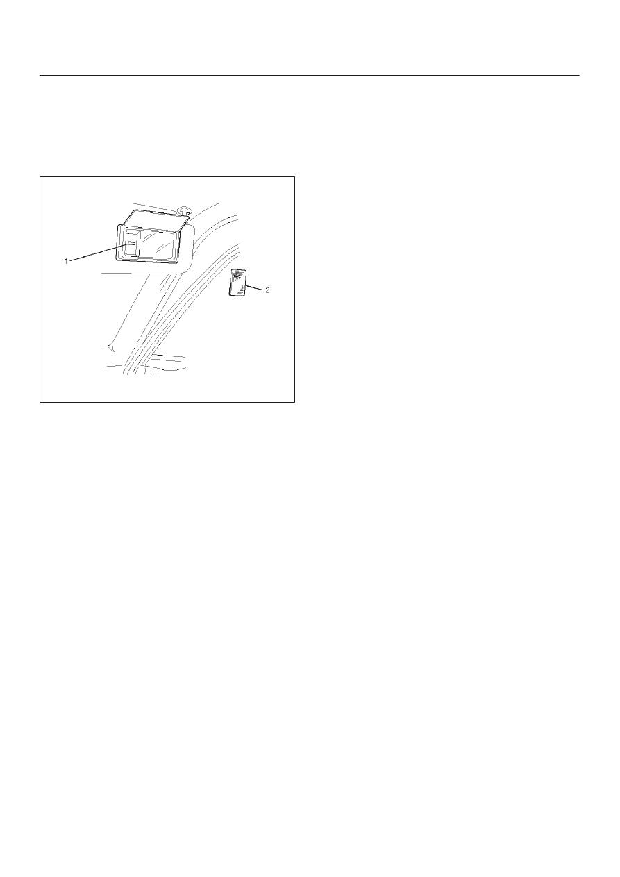
Vanity Mirror Illumination Bulb

Removal

1. Disconnect the battery ground cable.
2. Remove the lens(2).
3. Remove the bulb(1).

743RW007

Installation 

To install, follow the removal steps in the reverse order.

LIGHTING SYSTEM

8A–17

Starter Switch

Removal

1. Disconnect the battery ground cable.
2. Remove the front console assembly(1).

Refer to Instrument Panel Assembly in Body
Structure section.

3. Remove the lower cluster assembly(2).

Refer to the Instrument Panel Assembly in Body
Structure section.

4. Remove the instrument panel driver lower cover

assembly(3).
Refer to the Instrument Panel Assembly in Body
Structure section.

821RW024

5. Remove seven screws to remove the steering

cowl(6).

6. Disconnect the connector, remove the screw(4) and

then remove the starter switch(5).

431RW005

Installation

 To install, follow the removal steps in the reverse order
noting the following point.

1. When installing the steering cowl(10), be sure to pass

the harnesses through the route as shown in the
figure so that the starter switch harness(7), the
combination switch harness(8) and the inflator
module harness(9) will not get caught. 

431RW008

8A–18

LIGHTING SYSTEM

Lighting Switch (Combination Switch)

Removal

1. Disconnect the battery ground cable.
2. Remove the instrument panel driver lower cover(5).

Refer to the Instrument Panel Assembly in Body
Structure section.

3. Remove seven screws to remove the steering

cowl(4).

4. Disconnect the SDM (air bag controller) connector

located at lower of the instrument panel driver lower
cover.

5. Remove four fixing screws and disconnect the driver

inflator module connector to remove the driver inflator
module(3).

CAUTION: When carrying a live inflator module,
make sure the bag opening is pointed away from
you. In case of an accidental deployment, the bag will
then deploy with minimal chance of injury. Never
carry the inflator module by the wires or connector
on the underside of the module. 
 When placing a live inflator module on a bench or
other surface, always face the bag and trim cover up,
away from the surface. This is necessary so that a
free space is provided to allow the air bag to expand
in the unlikely event of accidental deployment. 

6. Remove the steering wheel(2). 

Refer to the Steering Wheel in Steering section.

7. Disconnect the SRS coil assembly connector,

remove four fixing screws to remove the SRS coil
assembly(1). 

8. Disconnect the lighting switch connector, remove four

fixing screws to remove the lighting switch(6). 

825RS039

Installation

To install, follow the removal steps in the reverse order,
noting the following points.

1. Check to see if the vehicle is in the straight driving

condition and turn the rotary section of the SRS coil
assembly provided to the upper surface of the lighting
switch (combination switch) counterclockwise fully
until it stops. 
Then from where it stops, turn it back about 3
rotations to set the alignment marks(7) together
before installing the steering wheel.

825RW099

2. Tighten the steering shaft nut to the specified torque.

Torque: 34 N·m (3.5 kg·m/25 lb ft)

3. When connect the double lock type of inflator module

connector, insert the connector completely and lock
at outside. 
Imperfect locking may cause malfunction of SRS
system circuit.

4. When installing the steering cowl(11), be sure to pass

the harnesses through the route as shown in the
figure so that the starter switch harness(8), the
combination switch harness(9) and inflator module
harness(10) will not get caught. 

431RW014

LIGHTING SYSTEM

8A–19

Fog Light Switch

Removal

1. Disconnect the battery ground cable.
2. Remove the front console assembly(1).

Refer to the Instrument Panel Assembly in Body
Structure section.

3. Remove the lower cluster assembly(2).

Refer to the Instrument Panel Assembly in Body
Structure section.

4. Remove the instrument panel driver lower cover

assembly(3).
Refer to the Instrument Panel Assembly in Body
Structure section.

821RW024

5. Remove the instrument panel cluster assembly(4).

Refer to the Instrument Panel Assembly in Body
Structure section.

6. Disconnect the connector and push the lock from the

back side of the instrument panel cluster assembly to
remove the fog light switch(5).

825RW027

Installation

To install, follow the removal steps in the reverse order,
noting the following point:

1. Push in the switch with your fingers until the switch is

locked securely.


Content   ..  631  632  633  634   ..