Opel Frontera UBS. Manual - part 560


  Index      Opel     Opel Frontera UBS - service repair manual 1998-2002 year


Search            


Content   ..  558  559  560  561   ..


Opel Frontera UBS. Manual - part 560


7A1–18 TRANSMISSION CONTROL SYSTEM (4L30–E)

OBD II Diagnostic Management System

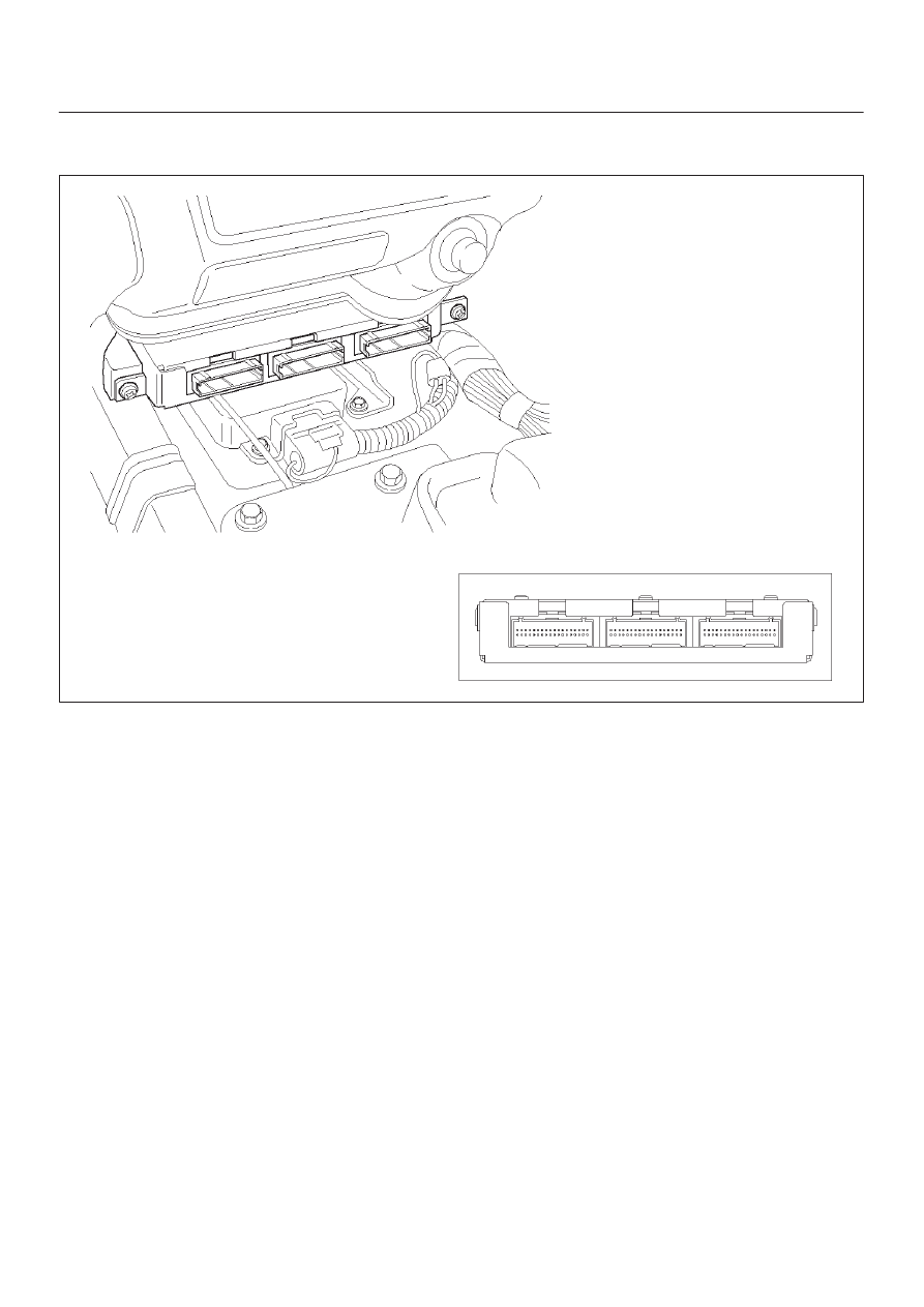
Powertrain Control Module (PCM) Location

C07RW005

Class 2 Serial Data Bus
OBD II technology requires a much more sophisticated
PCM than does OBD I technology. The OBD II PCM
diagnostic management system not only monitors
systems and components that can impact emissions, but
they also run active tests on these systems and
components. The decision making functions of OBD II
PCMs have also greatly increased. To accommodate this
expansion in diagnostic complexity, Isuzu engineers have
designed the Class 2 serial data bus, which meets SAE
J1850 recommended practice for serial data.
“Serial Data” refers to information which is transferred in a
linear fashion – over a single line, one bit at a time. A “Data
Bus” is an electronic pathway through which serial data
travels.

TROOPER previously used a 5 volt data bus called
UART, which is an acronym for “Universal Asynchronous
Receive and Transmit”. When neither the vehicle’s
control module nor the diagnostic tool, such as a Tech2,
are “talking,” the voltage level of the bus at rest is 5 volts.
The two computers talk to each other at a rate of 8,192
bits per second, by toggling or switching the voltage on
the data bus from 5 volts to ground.
Class 2 data, which is used on OBD II vehicles, is quite
different. Data is transferred at a rate of 10.4 kilobits per
second, and the voltage is toggled between zero and 7
volts.

TRANSMISSION CONTROL SYSTEM (4L30–E)

7A1–19

C07RT006

Class 2 data is also pulse width modulated. Each bit of
information can have one of two lengths: long or short. On
the other hand, UART data bits come in only one length
(short). The pulse width modulation of Class 2 data allows
better utilization of the data line.
The message carried on Class 2 data streams are also
prioritized. This means that if two devices try to
communication on the data line at the same time, only the
higher priority message will continue. The device with the
lower priority message must wait.

NOTE: The Class 2 data wire is always terminal 2 of the
new 16–terminal Data Link Connector (DLC).

16 – Terminal Data Link Connector (DLC)

OBD II standardizes Data Link Connector (DLC)
configurations. The DLC, formerly referred to as the
ALDL, will be a 16–terminal connector found on the lower
left side of the driver’s side instrument panel. All
manufacturers must conform to this 16–terminal
standard.

821RW262

7A1–20 TRANSMISSION CONTROL SYSTEM (4L30–E)

821RW263

810RT022

PIN 1 –

(Not used)

PIN 2 –

J1850 Bus + L line on 2–wire systems, or
single wire (Class 2)

PIN 3 –

(Not used)

PIN 4 –

Chassis ground pin

PIN 5 –

Signal ground pin

PIN 6 –

PCM diagnostic enable

PIN 7 –

(Not used)

PIN 8 –

(Not used)

PIN 9 –

Primary UART

PIN 10 –

(Not used)

PIN 11 –

(Not used)

PIN 12 –

ABS diagnostic or CCM diagnostic enable

PIN 13 –

SIR diagnostic enable

PIN 14 –

(Not used)

PIN 15 –

(Not used)

PIN 16 –

Battery power from vehicle unswitched (4
AMP MAX.)

Malfunction Indicator Lamp (MIL)

The Malfunction Indicator Lamp (MIL) looks the same as
the MIL you are already familiar with (“CHECK ENGINE”
lamp). However, OBD II requires that it illuminate under a
strict set of guidelines. Basically, the MIL is turned on
when the PCM detects a DTC that will impact the vehicle’s
emissions.
The MIL is under the control of the Diagnostic Executive.
The MIL will be turned on if a component or system which
has an impact on vehicle emissions indicates a
malfunction or fails to pass an emissions–related
diagnostic test. It will stay on until the system or
component passes the same test, for three consecutive
trips, with no emissions–related faults.

Types Of Diagnostic Trouble Codes (DTCs)

The Diagnostic Executive classifies Diagnostic Trouble
Codes (DTCs) into certain categories. Each type has
different requirements to set the code, and the Diagnostic
Executive will only illuminate the Malfunction Indicator
Lamp (MIL) for emissions–related DTCs. DTCs fall into
four categories: A, B, C, and D; only types A and B are
emission–related The following descriptions define these
categories:

TYPE A
Will store the DTC and turn on the MIL (“Check Engine”
lamp) on the first trip in which an emission–related
diagnostic test has run and reported a “test failed” to the
Diagnostic Executive.

TYPE B
Will store the DTC and turn on the MIL on the second
consecutive trip in which an emission–related diagnostic
test has run and reported a “test failed” to the Diagnostic
Executive. After one failure, the type B DTC is “armed,”
or prepared to store a history code and turn on the MIL if
a second failure occurs. One passed test will disarm a
type B DTC. Some special conditions apply to misfire and
fuel trim DTCs. For a type B DTC to store and turn on the
MIL, two ignition cycles are required.

TYPE C
Will store the DTC and turn on a “SERVICE” lamp
(“Check Trans” lamp) on the first trip that a
non–emission–related diagnostic test has run and
reported a “test failed” to the Diagnostic Executive. This
type of DTC will be used in future applications.

TYPE D
Will store a DTC but will not turn on the MIL on the first
trip that a non–emission–related diagnostic test has run
and reported a “test failed” to the Diagnostic Executive.
These codes can be very helpful for vehicle service when
the driver may comment about a condition, but the MIL did
not turn on.

Clear DTC

NOTE: If you clear the DTC (Diagnostic Trouble Codes)
you will not be able to read any codes recorded during the
last occurrence.

TRANSMISSION CONTROL SYSTEM (4L30–E)

7A1–21

NOTE: To use the DTC again to identify a problem, you
will need to reproduce the fault or the problem. This may
require a new test drive or just turning the ignition on (this
depends on the nature of the fault).

1. IF you have a Tech2:

1. Connect the Tech2 if it is still not connected

GOTHROUGH Tech2 OBD II CONNECTION.

2. Push “F4” and answer “Yes” to the question “Do

you really want to clear the codes?”

a. When a malfunction remains as it is the Tech2

displays “4L30E CODES NOT CLEARED”. This
means that the problem is still there or that the
recovery was not done. Please GOTO DTC
CHECK.

b. When a malfunction has been repaired and the

recovery is done. The Tech2 displays “4L30E
CODES CLEARED”.

2. IF you have no Tech2:

To clear the DTC, remove Fuse “Stop, A/T CONT”
(C–14, 15A) for at least 10 seconds.

DTC Check

1. Diagnostic Trouble Codes (DTC) have been identified

by Tech2.

2. You have written the list of the DTCs. The order of the

malfunctions has no meanings for this PCM. Usually
only one or two malfunctions should be set for a given
problem.

3. Check directly the DTCs you identified. The DTCs are

sorted by number. Refer to Diagnostic Trouble Code
(DTC) Identification in this section.

PCM Precaution

The PCM can be damaged by:

1. Electrostatic discharge
2. The short circuit of some terminals to voltage or to

ground.

Electrostatic Discharge Damage Description:

1. Electronic components used to control systems are

often designed to carry very low voltage, and are very
susceptible to damage caused by electrostatic
discharge. It is possible for less than 100 volts of
static electricity to cause damage to some electronic
components. By comparison, it takes as much as
4,000 volts for a person to even feel the zap of a static
discharge.

2. There are several ways for a person to become

statically charged. The most common methods of
charging are by friction and induction. An example of
charging by friction is a person sliding across a car
seat, in which a charge of as much as 25,000 volts
can build up. Charging by induction occurs when a
person with well insulated shoes stands near a highly
charged object and momentarily touches ground.
Charges for the same polarity are drained off, leaving
the person highly charged with the opposite polarity.
Static charges of either type can cause damage,
therefore, it is important to use care when handling
and testing electronic components.

NOTICE:

  To prevent possible electrostatic

discharge damage:

1. Do not touch the PCM connector pins or soldered

components on the PCM circuit board.

2. Be sure to follow the guidelines listed below if

servicing any of these electronic components:

3. Do not open the replacement part package until it is

time to install the part.

4. Avoid touching electrical terminals of the part.
5. Before removing the part from its package, ground

the package to a known good ground on the vehicle.

6. Always touch a known good ground before handling

the part. This step should be repeated before
installing the part if the part has been handled while
sliding across the seat, while sitting down from a
standing position or while walking some distance.

Information On PCM

1. The Powertrain Control Module (PCM) is located in

the center console and is the control center of the
electronic transmission control system.

2. The PCM must be maintained at a temperature below

185

°

F (85

°

C) at all times. This is most essential if the

vehicle is put through a paint baking process. The
PCM will become inoperative if its temperature
exceeds 85

°

C (185

°

F). Therefore, it is

recommended that the PCM be removed or that
temporary insulation be placed around the PCM
during the time the vehicle is in a paint oven or other
high temperature process.

3. The PCM is designed to process the various inputs

and then respond by sending the appropriate
electrical signals to control transmission upshift,
downshift, shift feel and torque converter clutch
engagement.

4. The PCM constantly interprets information from the

various sensors, and controls the systems that affect
transmission and vehicle performance. By analyzing
operational problems, the PCM is able to perform a
diagnostic function by displaying DTC(s) and aid the
technician in making repairs.

Intermittent Conditions

If the Tech2 displays a diagnostic trouble code as
intermittent, or if after a test drive a DTC does not
reappear though the detection conditions for this DTC are
present, the problem is most likely a faulty electrical


Content   ..  558  559  560  561   ..