Opel Frontera UBS. Manual - part 499
 

  Index      Opel     Opel Frontera UBS - service repair manual 1998-2002 year


Search            


Content   ..  497  498  499  500   ..


Opel Frontera UBS. Manual - part 499


6E–126

4JX1–TC ENGINE DRIVEABILITY AND EMISSIONS

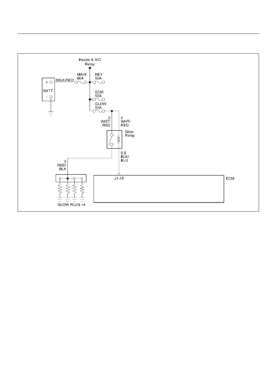
Diagnostic Trouble Code (DTC) P0380 (Flash DTC 66) 

Glow Relay Circuit Open/Short

060RW132

Circuit Description

Glow relay circuit receives current through Glow 50A fuse
from the battery. Glow relay is circuited to Glow plug.

Action Taken When the DTC Sets

D

The ECM will store conditions which were present
when the DTC was set as Freeze Frame and in the
Failure Records data.

Conditions for Clearing the MIL/DTC

D

DTC P0380 can be cleared by using the Tech 2 “Clear
Info” function or by disconnecting the ECM battery
feed.

Diagnostic Aids

An intermittent may be caused by a poor connection,
rubbed-through wire insulation or a wire broken inside the
insulation.  Check for:

D

Poor connection – Inspect the ECM harness and
connectors for improper mating, broken locks,
improperly formed or damaged terminals, and poor
terminal-to-wire connection.

D

Damaged harness – Inspect the wiring harness for
damage.

6E–127

4JX1–TC ENGINE DRIVEABILITY AND EMISSIONS

DTC P0380 – Glow Relay Circuit Open/Short


Step

Action

Value(s)

Yes

No

1

Was the “On-Board Diagnostic (OBD) System Check”
performed?

—

Go to 

Step 2

Go to 

OBD

System

Check

2

Attempt to start the engine.

Does the engine start?

—

Go to 

Step 3

Go to 

Chart 3

3

1. Review and record Failure Records information.
2. Clear DTC P0380.
3. Start the engine and idle for 1 minute.
4. Observe DTCs.

Is DTC P0380 set?

—

Go to 

Step 4

Refer to

Diagnostic

Aid

4

Check the glow fuse 50A.

Is the glow fuse 50A damage?

—

Go to 

Step 5

Go to 

Step 6

5

Replace the glow fuse 50A.

Is the action complete?

—

Verify repair

Go to 

Step 6

6

1. Ignition “OFF.”
2. Check for an open or a short to ground in the Glow

relay circuit between the Glow relay connector and
the ECM harness connector.

3. If a problem is found, repair as necessary.

Was a problem found?

—

Verify repair

Go to 

Step 7

7

Check the connections at the Glow relay and replace
the terminals if necessary.

Did any terminals require replacement?

—

Verify repair

Go to 

Step 8

8

Replace the Glow relay.

Is the action complete?

—

Verify repair

Go to 

Step 9

9

Check the connections at the ECM and replace the
terminals if necessary.

Did any terminals require replacement?

—

Verify repair 

Go to 

Step 10

10

Replace the ECM (Refer to the Data Programming in
Case of ECM change).

Is the action complete?

—

Verify repair

—

6E–128

4JX1–TC ENGINE DRIVEABILITY AND EMISSIONS

Diagnostic Trouble Code (DTC) P0381 (Flash DTC 67)

 Glow Lamp Circuit Open/Short

060RW136

Circuit Description

Glow Lamp Circuit receives current through Meter 10A
fuse, Glow lamp being circuited to ECM.

Action Taken When the DTC Sets

D

The ECM will store conditions which were present
when the DTC was set as Freeze Frame and in the
Failure Records data.

Conditions for Clearing the MIL/DTC

D

DTC P0381 can be cleared by using the Tech 2 “Clear
Info” function or by disconnecting the ECM battery
feed.

Diagnostic Aids

An intermittent may be caused by a poor connection,
rubbed-through wire insulation or a wire broken inside the
insulation.  Check for:

D

Poor connection – Inspect the ECM harness and
connectors for improper mating, broken locks,
improperly formed or damaged terminals, and poor
terminal-to-wire connection.

D

Damaged harness – Inspect the wiring harness for
damage.

6E–129

4JX1–TC ENGINE DRIVEABILITY AND EMISSIONS

DTC P0381 – Glow Lamp Circuit Open/Short


Step

Action

Value(s)

Yes

No

1

Was the “On-Board Diagnostic (OBD) System Check”
performed?

—

Go to 

Step 2

Go to 

OBD

System

Check

2

1. Review and record Failure Records information.
2. Clear DTC P0381.
3. Observe DTCs.

Is DTC P0381 set?

—

Go to 

Step 3

Refer to

Diagnostic

Aid

3

1. Ignition “OFF.”
2. Remove the Meter assembly.
3. Check for an open or a short to ground in the Glow

Lamp circuit. 

4. If a problem is found, repair as necessary. 
(On electric bulb of the Glow Lamp, The Glow Lamp
harness circuit)

Was a problem found?

—

Refer to the

Meter in

Electric

section 8

Go to 

Step 4

4

Check the connections at the ECM and replace the
terminals if necessary.

Did any terminals require replacement?

—

Verify repair 

Go to 

Step 5

5

Replace the ECM (Refer to the Data Programming in
Case of ECM change).

Is the action complete?

—

Verify repair

—


Content   ..  497  498  499  500   ..