Opel Frontera UBS. Manual - part 464


  Index      Opel     Opel Frontera UBS - service repair manual 1998-2002 year


Search            


Content   ..  462  463  464  465   ..


Opel Frontera UBS. Manual - part 464


6D – 12 ENGINE ELECTRICAL

2) Inspect the brush springs for wear, damage or other

abnormal conditions.

Standard: 28 – 35 N (2.9 – 3.6 kg/6.4 – 7.9 lb)
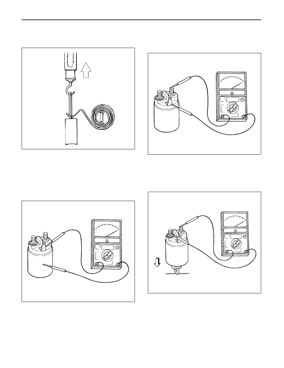
Magnetic switch

1) Continuity of shunt coil

Check for continuity between terminals S and coil
case.
Replace, if there is not continuity (i.e., coil is
disconnected.)

2) Continuity of series coil

Check for continuity between terminals S and M.
Replace, if there is no continuity (i.e., coil is
disconnected).

3) Continuity of contacts

With the plunger faced downward, push down the
magnetic switch. In this state, check for continuity
between terminals B and M. Replace, if there is no
continuity (i.e., contacts are faulty).

065RW052

065RW017

065RW018

065RW016

ENGINE ELECTRICAL 6D – 13

Pinion

1) Check by hand to see if the pinion rotates smoothly

in the dirve direction, or if it is locked when it is
rotated reversely.
If not, replace the pinion. 

Yoke assembly

1) Check the magnet inside the yoke.

Replace the yoke assembly if it is broken. 

REASSEMBLY

To install, follow the removal steps in the reverse order,
noting the following points:

Grease application places

1) Gears in reduction gear
2) Shift lever operating portion
3) Sliding potion of pinion
4) Plunger sliding portion of magnetic switch 

Pinion jump-out dimension

1) Connect the (+) cable of battery to terminal S and

the (–) cable to terminal M. Turn the switch on, and
measure pinion travel dimension “L” in thrust
direction from the jump-out position.

In measuring the dimension, pull the pinion out a little in
the arrow direction.

Dimension L: 0.3 – 1.5 mm (0.01 – 0.06 in)

If the measured value is out of standard, adjust the of
shims.

Legend

(1) Shim

065RW048

S

+

L

M

065RW054

1

065RW053

6D – 14 ENGINE ELECTRICAL

MAGNETIC SWITCH

Pull-out test

Connect the magnetic switch to the battery as shown.
The negative side to the “M” terminal and the magnetic
switch body (housing); the positive side to the “S”
terminal. If the pinion has been ejected, the pull-in coil
is satisfactory.

Legend

(1) Terminal “S”
(2) Terminal “M”
(3) Starter
(4) For Return Test
(5) For Hold-In Test

Hold-in test

1. Next disconnect the “M” terminal.
2. The pinion should remain in the ejected position.

Return test

When the switch body is disconnected, the pinion
should return quickly.

2

1

5

3

4

065RW055

ENGINE ELECTRICAL 6D – 15

CHARGING SYSTEM

GENERAL DESCRIPTION

GENERATOR

CHARGING CIRCUIT

The charging system is the IC integral regulator
charging system and its main components are
connected as shown in Figure.
The regulator is a solid state type and it is mounted
along with the brush holder assembly inside the
generator installed on the rear end cover.

The generator does not require particular maintenance
such as voltage adjustment. The rectifier connected to
the stator coil has nine diodes to transform A.C. voltage
into D.C. voltage. This D.C. voltage is connected to the
output terminal of generator.

A06RW001

Condenser

Generator

Stator Coil

IC Regulator

Starter
SW

Rotor Coil

Battery

P

F

E

B S

L

Relay

B

S

L

QOS

065R200028


Content   ..  462  463  464  465   ..