Opel Frontera UBS. Manual - part 435
6A – 30 ENGINE MECHANICAL
ENGINE MOUNT (RH)
REMOVAL
1. Disconnect battery ground cable
2. Hang the engine assembly.
3. Rubber engine mount.
1) Remove bolts from chassis frame bracket.
2) Remove nuts from rubber engine mount and
engine mounting bracket.
4. Remove bolt which is fixed between engine and
mounting bracket then remove the engine mounting
bracket.
INSTALLATION
•
Tighten the fixing bolts to the specified torque.
1. Engine mounting bracket to cylinder block.
Torque : 40 N·m (4 kg·m/29 lb ft) (for M10)
127 N·m (13 kg·m/94 lb ft) (for M14)
2. Rubber engine mount to chassis frame and engine
mounting bracket.
Torque :40 N·m (4 kg·m/29 lb ft)
4
3
1
2
022RW018
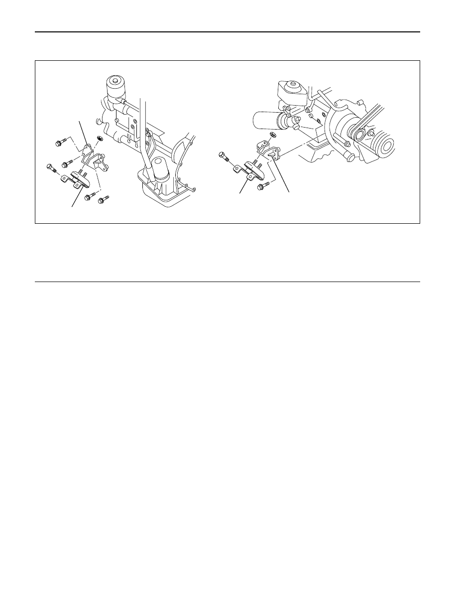
Legend
(1)
Rubber Engine Mount (LH)
(2)
Engine Mounting Bracket (LH)
(3)
Rubber Engine Mount (RH)
(4)
Engine Mounting Bracket (RH)