Opel Frontera UBS. Manual - part 420
 

  Index      Opel     Opel Frontera UBS - service repair manual 1998-2002 year


Search            


Content   ..  418  419  420  421   ..


Opel Frontera UBS. Manual - part 420


STARTING SYSTEM 6D2 – 9

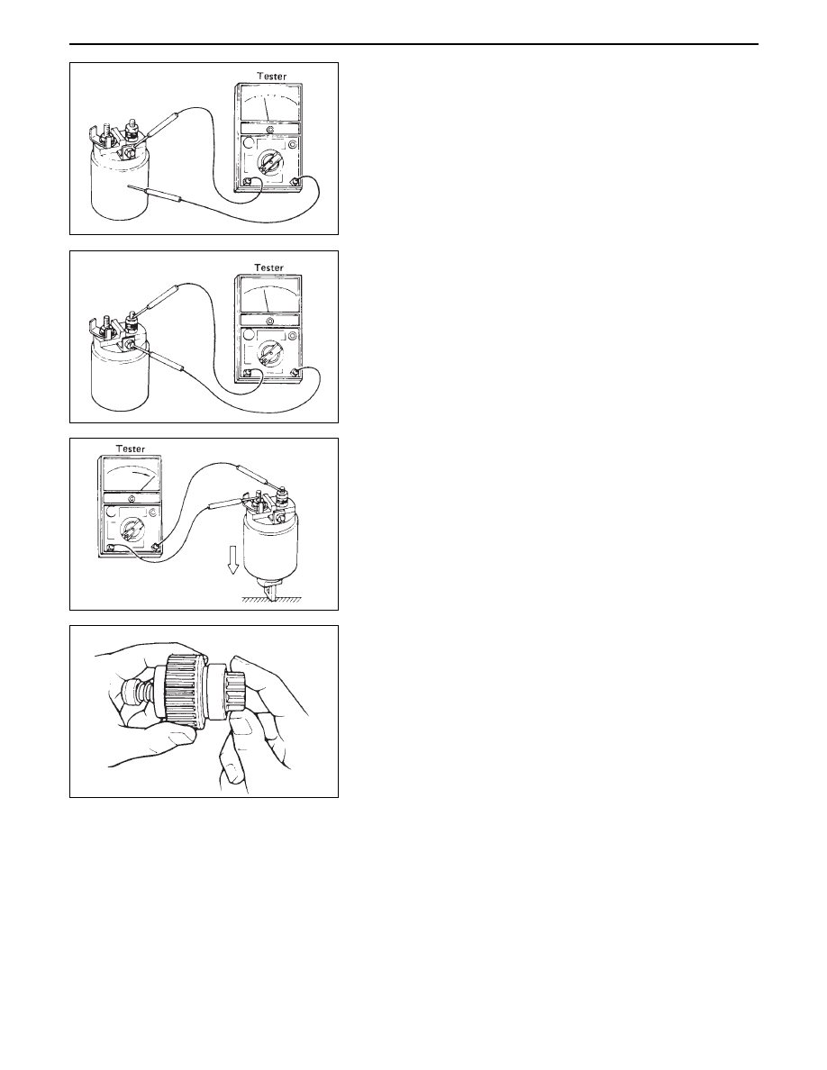
Magnetic switch

•

Continuity of shunt coil
Check for continuity between terminals S and coil
case.
Replace, if there is no continuity (i.e., coil is
disconnected).

•

Continuity of series coil
Check for continuity between terminals S and M.
Replace, if there is no continuity (i.e., coil is
disconnected).

Pinion

•

Check if the pinion rotates smoothly in drive direction
by hand, or if it is locked when it is rotated reversely.
If not, replace the pinion.

Yoke assembly

•

Check a magnet inside the yoke.
Replace the yoke assembly if it is broken.

•

Continuity of contacts
With the plunger faced downward, push down the
magnetic switch. In this state, check for continuity
between terminals B and M. Replace, if there is no
continuity (i.e., contacts are faulty).

6D2 – 10 STARTING SYSTEM

REASSEMBLY

To install, follow the removal steps in the reverse order,
noting the following points:

Grease application places

•

Gears in reduction gear

•

Shift lever operating portion

•

Sliding portion of pinion

•

Plunger sliding portion of magnetic switch

Pinion jump-out dimension

•

Connect the (+) cable of battery to terminal S and the
(–) cable to terminal M. Turn the switch on, and
measure pinion travel dimension “L” in thrust
direction from the jump-out   position.

In measuring the dimension, pull the pinion out a little in
the arrow direction.

If the measured value is out of standard, adjust the of
shims.

Dimension

L

0.3 - 1.5 (0.01 - 0.06)

Standard

mm (in)

STARTING SYSTEM 6D2 – 11

MAGNETIC SWITCH
Pull-out test

Connect the magnetic switch to the battery as shown.
The negative side to the “M” terminal and the magnetic
switch  body (housing); the positive side to the “S”
terminal.  If the pinion  has been ejected, the pull-in coil is
satisfactory

Hold-in test

1.

Next disconnect the “M” terminal.

2.

The pinion should remain the ejected position

Return test

When the switch body is disconnected, the pinion should
return quickly

6D2 – 12 STARTING SYSTEM

MEMO


Content   ..  418  419  420  421   ..