Opel Frontera UBS. Manual - part 414
FUEL SYSTEM 6C – 13
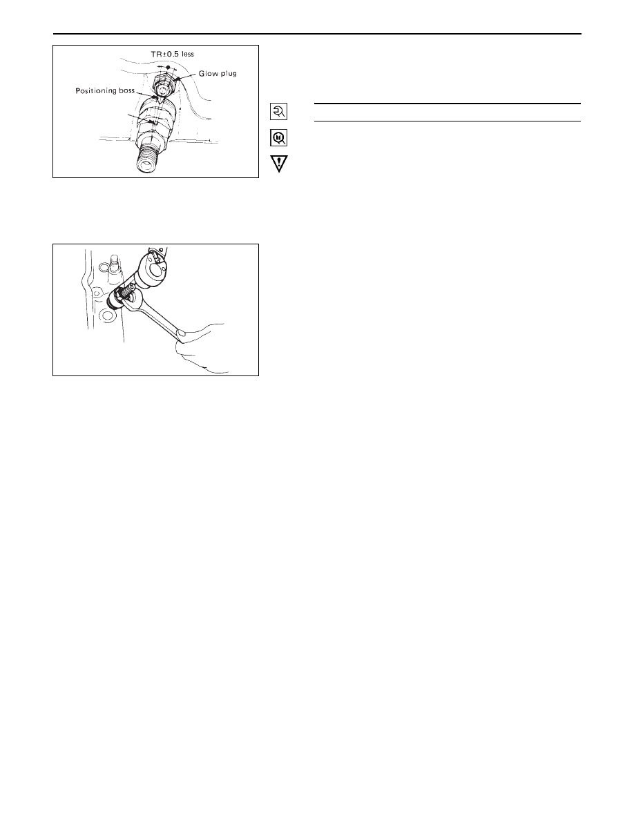
•
Apply a wrench as illustrated, and tighten the
holder nut to the specified torque using a special
tool.
wrench: nozzle holder 5-8840-0259-0
CAUTION
•
After tightening the holder nut, make sure that the
drilled hole makes ± 5° or smaller with the cylinder
head-side positioning boss.
•
When mounting leak off pipe, injection nozzle and
pipe, clean then with air so that dust may not enter.
4.
Leak Off Pipe
•
Mount using a new copper waker
3.
Injection Pipe
•
Connect injection pipe to nozzle holder.
•
Tighten the injection pump side.
•
Fit pipe clip in specified position.
2.
Air Cleaner Cover & Air duct
1.
Intercooler Assembly
•
Refer to “Intercooler” installation in section 6A2.
64 (6.5/47)
N·m (Kg·m/lb.ft)