Opel Frontera UBS. Manual - part 407
 

  Index      Opel     Opel Frontera UBS - service repair manual 1998-2002 year


Search            


Content   ..  405  406  407  408   ..


Opel Frontera UBS. Manual - part 407


4JG2-NA/4JG2-TURBO ENGINE 6A2 – 49

3.

Cooling Fan Assembly

•

Remove cooling fan asm fixing nuts, cooling fan
asm, fan pulley and center.

4.

Radiator Assembly

•

Remove bracket and radiator asm.

5.

Air Cleaner Cover & Air Duct

6.

Intercooler Assembly (4JG2 -T only)

•

(Refer to Intercooler removal steps in this section)

7.

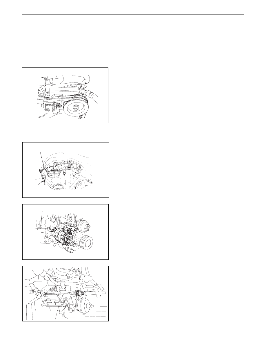
P/S Pump Drive Belts

•

Loosen P/S pump fixing bolts and adjusting bolt
and remove two drive belts.

8.

P/S Pump Assembly

•

Remove two fixing bolts (front side), a fixing nut
(rear side) and support P/S pump asm with oil
hoses by tying to body side.

9.

Engine Ground Cable

•

Disconnect ground cable from A/C compressor
bracket.

10. AC Generator Harness

•

Disconnect B terminal and harness connector
from AC generator.

11. A/C Compressor Assembly

•

Remove A/C compressor fixing bolt (rear under
side of compressor) by using a long extension bar
at under side of wheel arch.

•

Disconnect magnetic clutch harness connector.

•

Remove fixing bolts (upper and front lower side
of compressor) and set A/C compressor asm with
pipe lines on battery carrier.

12. Vacuum Hose: Vacuum Pump

•

Disconnect vacuum hose from vacuum pump.

13. Starter Harness

•

Disconnect B terminal and put cable harness close
to chassis side.

•

Disconnect S terminal connector.

14. Engine Harness.

•

Disconnect engine harness close to engine side.

15. Accelerater Cable

•

Loosen locking nut at bracket and disconnect
accelerater cable from injection pump control
lever.

16. Fuel Hoses

•

Disconnect fuel hoses from injection pump side
and take care not to spill fuel and enter dust.

17. Engine Ground Cable

•

Disconnect ground cable from left rear side of
timing gear case.

6A2 – 50 4JG2-NA/4JG2-TURBO ENGINE

18. Vacuum Hose : Vacuum Tank

•

Disconnect vacuum hose from vacuum pump
side.

19. Glow Plug Harness

20. Transmission Assembly

•

Install special tools (engine hangers) in front right
and left rear sides of cylinder head.

•

Front right side; use the ground cable fixing bolt
on A/C compressor bracket.

•

Left rear side; fix hanger together with oil cooler
hose clip.
Engine hanger: 5-8840-2032-0

•

Left engine carefully by using hoist.

21. Engine Mounting

•

Remove fixing bolts (both left and right side)
using extension bar and box wrench at under side
of wheel arches.

22. Engine Assembly

•

Install special tools (engine hangers) in left rear
and front right sides of cylinder head.

•

Lift engine carefully by using hoist.

•

Lift front part of engine higher than rear part of it.

•

Take out engine asm taking care not to damage
full pipes, brake pipes and etc.

INSTALLATION

22. Engine Assembly

•

Position engine mountings by using hoist.

21. Engine Mounting

•

After all fixing bolts (left: two bolts, rights: two
bolts) were inserted to every holes, and engine
asm and tighten fixing bolts to the specified
torque.

40 (4.1/30)

N·m(Kg·m/lb·ft)

20. Transmission Assembly

•

Refer to transmission installation steps
in section 7.

19. Glow Plug Harness

18 Vacuum Hose: Vacuum Tank

17. Engine Ground Cable

16. Fuel Hose

15. Accelerator Cable

•

Refer to accelerater cable installation steps in
section 6C.

4JG2-NA/4JG2-TURBO ENGINE 6A2 – 51

14. Engine Harness.

13. Starter Harness

12. Vacuum Hose: Vacuum Pump

11. A/C Compressor Assembly

•

Tighten temporarily fixing bolts (upper and front
lower sides of compressor).

•

Tighten fixing bolt (rear under side of
compressor) to the specified torque by using
along extension bar and torque wrench at under
side of wheel arch.

•

Tighten fixing bolts (front upper and lower sides
of compressor) to the specified torque.

40 (4.1/30)

N·m(Kg·m/lb·ft)

6A2 – 52 4JG2-NA/4JG2-TURBO ENGINE

6.

Intercooler Assembly (4JG2-T Only)

•

Refer to intercooler installation steps in  this
section.

5.

Air Cleaner Cover & Duct

4.

Radiator Assembly

•

Install cushion rubber in under left and right part
of radiator and position radiator.

•

Fix radiator by bracket.

3.

Cooling Fan Assembly

•

Install cooling fan asm and tighten fixing bolts to
the specified torque.

2.

Fan Shroud

1.

Radiator Hose

•

Connect upper and lower hose to engine side.

•

Pour coolant in to radiator.

•

Install battery.

•

Connect window washer hose.

10. A.C. Generator Harness

9.

Engine Ground Cable

•

Attached ground cable to A/C compressor bracket.

8.

P/S Pump Assembly

•

Install P/S pump asm in engine and tighten
temporarily fixing nut.

7.

P/S Pump Drive Belt

•

Install drive belts adjust belt tension by adjusting
bolt and tighten locking bolt to the specified
torque.

•

Refer to “Drive Belt Adjustment” in section 6B.

8 (0.8/69)

N·m(Kg·m/lb·in)

40 (4.1/30)

N·m(Kg·m/lb·ft)


Content   ..  405  406  407  408   ..