Opel Frontera UBS. Manual - part 358


  Index      Opel     Opel Frontera UBS - service repair manual 1998-2002 year


Search            


Content   ..  356  357  358  359   ..


Opel Frontera UBS. Manual - part 358


6E–338

ENGINE DRIVEABILITY AND EMISSIONS

RPM.  A failure in the MAF sensor or circuit will set DTC
P0101, DTC P0102, or DTC P0103.

0007

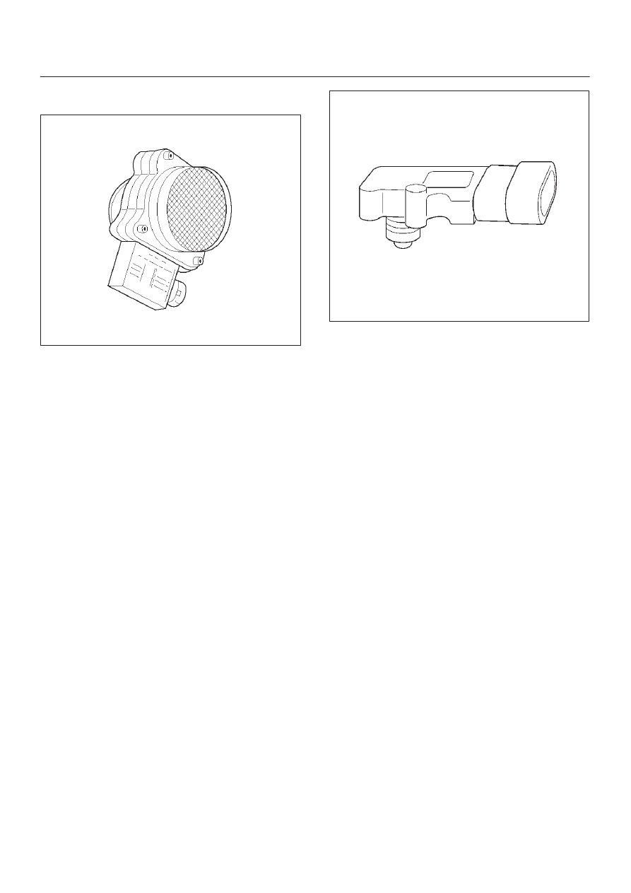
Manifold Absolute Pressure (MAP) Sensor

The manifold absolute pressure (MAP) sensor responds
to changes in intake manifold pressure (vacuum).  The
MAP sensor signal voltage to the PCM varies from below
2 volts at idle (high vacuum) to above 4 volts with the
ignition ON, engine not running or at wide-open throttle
(low vacuum).
The MAP sensor is used to determine the following:

D

Manifold pressure changes while the linear EGR flow
test diagnostic is being run.  Refer to 

DTC P0401.

D

Engine vacuum level for other diagnostics.

D

Barometric pressure (BARO).

If the PCM detects a voltage that is lower than the
possible range of the MAP sensor, DTC P0107 will be set.
A signal voltage higher than the possible range of the
sensor will set DTC P0108.  An intermittent low or high
voltage will set DTC P1107 or DTC P1106, respectively.
The PCM can detect a shifted MAP sensor.  The PCM
compares the MAP sensor signal to a calculated MAP
based on throttle position and various engine load factors.
If the PCM detects a MAP signal that varies excessively
above or below the calculated value, DTC P0106 will set.

055RW004

Powertrain Control Module (PCM)

The powertrain control module (PCM) is located in the
passenger compartment below the center console.  The
PCM controls the following:

D

Fuel metering system.

D

Transmission shifting (automatic transmission only).

D

Ignition timing.

D

On-board diagnostics for powertrain functions.

The PCM constantly observes the information from
various sensors.  The PCM controls the systems that
affect vehicle performance.  The PCM performs the
diagnostic function of the system.  It can recognize
operational problems, alert the driver through the MIL
(Service Engine Soon lamp), and store diagnostic trouble
codes (DTCs).  DTCs identify the problem areas to aid the
technician in making repairs.
This engine uses 2 different control modules:

D

IPCM-6KT for automatic transmission-equipped
vehicles.

D

ISFI-6 for manual transmission-equipped vehicles.

PCM Function

The PCM supplies either 5 or 12 volts to power various
sensors or switches.  The power is supplied through
resistances in the PCM which are so high in value that a
test light will not light when connected to the circuit.  In
some cases, even an ordinary shop voltmeter will not give
an accurate reading because its resistance is too low.
Therefore, a digital voltmeter with at least 10 megohms
input impedance is required to ensure accurate voltage
readings. Tool J 39200 meets this requirement.  The PCM
controls output circuits such as the injectors, IAC, cooling
fan relays, etc., by controlling the ground or the power
feed circuit through transistors of following device.

D

Output Driver Module (ODM)

6E–339

ENGINE DRIVEABILITY AND EMISSIONS

0005

PCM Components

The PCM is designed to maintain exhaust emission levels
to government mandated standards while providing
excellent driveability and fuel efficiency.  The PCM
monitors numerous engine and vehicle functions via
electronic sensors such as the throttle position (TP)
sensor, heated oxygen sensor (HO2S), and vehicle
speed sensor (VSS).  The PCM also controls certain
engine operations through the following:

D

Fuel injector control

D

Ignition control module

D

Knock sensor

D

Automatic transmission shift functions

D

Cruise control

D

A/C clutch control

PCM Voltage Description

The PCM supplies a buffered voltage to various switches
and sensors.  It can do this because resistance in the
PCM is so high in value that a test light may not illuminate
when connected to the circuit.  An ordinary shop
voltmeter may not give an accurate reading because the
voltmeter input impedance is too low.  Use a 10-megohm
input impedance digital voltmeter (such as J 39200) to
assure accurate voltage readings.
The input/output devices in the PCM include
analog-to-digital converters, signal buffers, counters,
and special drivers.  The PCM controls most components
with electronic switches which complete a ground circuit
when turned “ON.”  These switches are arranged in
groups of 4 and 7, called either a surface-mounted quad
driver module (QDM), which can independently control up
to 4 output terminals, or QDMs which can independently
control up to 7 outputs.  Not all outputs are always used.

PCM Input/Outputs

Inputs – Operating Conditions Read

D

Air Conditioning “ON” or “OFF” 

D

Engine Coolant Temperature

D

Crankshaft Position

D

Exhaust Oxygen Content

D

Electronic Ignition

D

Manifold Absolute Pressure

D

Battery Voltage

D

Throttle Position

D

Vehicle Speed

D

Fuel Pump Voltage

D

Power Steering Pressure

D

Intake Air Temperature

D

Mass Air Flow

D

Engine Knock

D

Camshaft Position

Outputs – Systems Controlled

D

Exhaust Gas Recirculation (EGR)

D

Ignition Control

D

Fuel Control

D

Idle Air Control

D

Electric Fuel Pump

D

Air Conditioning

D

Diagnostics

– Malfunction Indicator Lamp (Service Engine Soon

lamp)

– Data Link Connector (DLC)
– Data Output

D

Transmission Control Module

D

Alternator Gain Control

PCM Service Precautions

The PCM is designed to withstand normal current draws
associated with vehicle operation.  Avoid overloading any
circuit.  When testing for opens and shorts, do not ground
or apply voltage to any of the PCM’s circuits unless
instructed to do so.  These circuits should only be tested
Tech-2.  The PCM should remain connected to the PCM
or to a recommended breakout box.

Reprogramming The PCM

The Trooper allow reprogramming of the PCM without
removing it from the vehicle .  This provides a flexible and
cost-effective method of making changes in software
calibrations.
The service programming system (SPS) will not allow
incorrect software programming or incorrect calibration
changes.
Refer to the UBS 98model year Immobilizer Workshop
Manual.

Throttle Position (TP) Sensor

The throttle position (TP) sensor is a potentiometer
connected to the throttle shaft on the throttle body.  The
PCM monitors the voltage on the signal line and
calculates throttle position.  As the throttle valve angle is
changed (accelerator pedal moved), the TP sensor signal
also changes.  At a closed throttle position, the output of

6E–340

ENGINE DRIVEABILITY AND EMISSIONS

the TP sensor is low.  As the throttle valve opens, the
output increases so that at wide open throttle (WOT), the
output voltage should be above 4 volts.
The PCM calculates fuel delivery based on throttle valve
angle (driver demand).  A broken or loose TP sensor may
cause intermittent bursts of fuel from an injector and
unstable idle because the PCM thinks the throttle is
moving.  A hard failure in the TP sensor 5-volt reference
or signal circuits will set a DTC P0123.  A hard failure with
the TP sensor ground circuit may set  DTC P0123.  Once
a DTC is set, the PCM will use an artificial default value
based on engine RPM and mass air flow for the throttle
position, and some vehicle performance will return.  A
high idle may result when DTC P0123 is set.  The PCM
can also detect a shifted TP sensor.  The PCM monitors
throttle position and compares the actual TP sensor
reading to a predicted TP value calculated from engine
speed.  If the PCM detects an out-of-range condition,
DTC P0121 will be set.

0021

Transmission Fluid Temperature (TFT)
Sensor

The transmission fluid temperature sensor is a thermistor
which changes its resistance based on the temperature of
the transmission fluid.  For a complete description of the
TFT sensor, refer to 

4L30-E Automatic Transmission

Diagnosis.
A failure in the TFT sensor or associated wiring will cause
DTC P0712 or DTC P0713 to set.  In this case, engine
coolant temperature will be substituted for the TFT
sensor value and the transmission will operate normally.

Transmission Range Switch

IMPORTANT:

The vehicle should not be driven with the

transmission range switch disconnected; idle quality will
be affected.
The four inputs from the transmission range switch
indicate to the PCM which position is selected by the
transmission selector lever.  This information is used for
ignition timing, EVAP canister purge, EGR and IAC valve
operation.

For more information on the transmission on the
transmission range switch, refer to 

4L30-E Automatic

Transmission.

Vehicle Speed Sensor (VSS)

The PCM determines the speed of the vehicle by
converting a plusing voltage signal from the vehicle speed
sensor (VSS) into miles per hour. The PCM uses this
signal to operate the cruise control, speedometer, and the
TCC and shift solenoids in the transmission. For more
information on the TCC and shift solenoids, refer to
4L30-E Automatic Transmission.

0008

Use of Circuit Testing Tools

Do not use a test light to diagnose the powertrain
electrical systems unless specifically instructed by the
diagnostic procedures.  Use Connector Test Adapter Kit J
35616 whenever diagnostic procedures call for probing
connectors.

Aftermarket Electrical and Vacuum
Equipment

Aftermarket (add-on) electrical and vacuum equipment is
defined as any equipment which connects to the vehicle’s
electrical or vacuum systems that is installed on a vehicle
after it leaves the factory.  No allowances have been
made in the vehicle design for this type of equipment.

NOTE: No add-on vacuum equipment should be added
to this vehicle.

NOTE: Add-on electrical equipment must only be
connected to the vehicle’s electrical system at the battery
(power and ground).

Add-on electrical equipment, even when installed to
these guidelines, may still cause the powertrain system to
malfunction. This may also include equipment not
connected to the vehicle electrical system such as
portable telephones and radios.  Therefore, the first step
in diagnosing any powertrain problem is to eliminate all
aftermarket electrical equipment from the vehicle.  After

6E–341

ENGINE DRIVEABILITY AND EMISSIONS

this is done, if the problem still exists, it may be diagnosed
in the normal manner.

Electrostatic Discharge Damage

Electronic components used in the PCM are often
designed to carry very low voltage.  Electronic
components are susceptible to damage caused by
electrostatic discharge.  Less than 100 volts of static
electricity can cause damage to some electronic
components.  By comparison, it takes as much as 4000
volts for a person to feel even the zap of a static
discharge.

TS23793

There are several ways for a person to become statically
charged.  The most common methods of charging are by
friction and induction.

D

An example of charging by friction is a person sliding
across a vehicle seat.

D

Charge by induction occurs when a person with well
insulated shoes stands near a highly charged object
and momentary touches ground.  Charges of the
same polarity are drained off leaving the person
highly charged with the opposite polarity.  Static
charges can cause damage, therefore it is important
to use care when handling and testing electronic
components.

NOTE: To prevent possible electrostatic discharge
damage, follow these guidelines:

D

Do not touch the PCM connector pins or soldered
components on the PCM circuit board.

D

Do not touch the knock sensor module component
leads.

D

Do not open the replacement part package until the
part is ready to be installed.

D

Before removing the part from the package, ground
the package to a known good ground on the vehicle.

D

If the part has been handled while sliding across the
seat, while sitting down from a standing position, or
while walking a distance, touch a known good ground
before installing the part.

Upshift Lamp

Refer to 

Manual Transmission.

General Description (Air Induction)

Air Induction System

The air induction system filters contaminants from the
outside air, and directs the progress of the air as it is
drawn into the engine.  A remote-mounted air cleaner
prevents dirt and debris in the air from entering the
engine.  The air duct assembly routes filtered air to the
throttle body.  Air enters the engine by to following steps:
1. Through the throttle body.
2. Into the common chamber.
3. Through the cylinder head intake ports.
4. Into the cylinders.

055RV010

General Description (Fuel Metering)

Acceleration Mode

The PCM provides extra fuel when it detects a rapid
increase in the throttle position and the air flow.

Accelerator Controls

The accelerator control system is a cable-type system
with specific linkage adjustments.
Refer to 

Cable Adjustment.

Battery Voltage Correction Mode

When battery voltage is low, the PCM will compensate for
the weak spark by increasing the following:

D

The amount of fuel delivered.

D

The idle RPM.

D

Ignition dwell time.

CMP Signal

The PCM uses this signal to determine the position of the
number 1 piston during its power stroke, allowing the


Content   ..  356  357  358  359   ..