Opel Frontera UBS. Manual - part 332
6E–234
ENGINE DRIVEABILITY AND EMISSIONS
Diagnostic Trouble Code (DTC) P0502 VSS Circuit Low Input
D06RW019
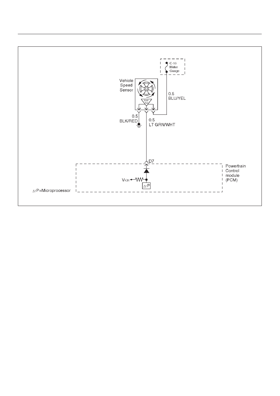
Circuit Description
The vehicle speed sensor has a magnet rotated by the
transmission output shaft. Attached to the sensor is a hall
effect circuit the interacts with the magnetic field treated
by the rotating magnet. A 12-volt operating supply for the
speed sensor hall circuit is supplied from the meter fuse.
The VSS pulses to ground the 9-volt signal sent from the
powertrain control module (PCM) on the reference circuit.
The PCM interprets vehicle speed by the number of
pulses to ground per second on the reference circuit.
Conditions for Setting the DTC
D
Engine is running.
D
Engine coolant temperature is above 60
°
C (140
°
F).
D
Engine speed is between 1800 RPM and 2500 RPM.
D
Throttle angle is between 10% and 40%.
D
Engine load is greater than 50 kPa.
D
MAP sensor indicates greater than 50 kPa manifold
pressure.
D
PCM detects no VSS signal for 12.5 seconds over a
period of 25 seconds.
Action Taken When the DTC Sets
D
The PCM will illuminate the malfunction indicator lamp
(MIL) the first time the fault is detected.
D
The PCM will store conditions which were present
when the DTC was set as Freeze Frame and in the
Failure Records data.
Conditions for Clearing the MIL/DTC
D
DTC P0502 can be cleared by using the Tech 2 “Clear
Info” function or by disconnecting the PCM battery
feed.
Test Description
Number(s) below refer to the step number(s) on the
Diagnostic Chart.
10. To avoid backprobing the VSS and possibly
damaging a seal or terminal, the VSS output can be
tested at the point where the transmission harness
connects to the engine harness. Power and ground
are applied by jumpers to the VSS through the
connectors which are located just in front of the air
cleaner assembly. The VSS signal is monitored
with a DVM as the rear driveshaft turns. The
wheels can be turned to rotate the driveshaft, or in
2-wheels-drive vehicles the driveshaft can be turned
directly.
12. The speedometer-to-PCM VSS signal wire is
spliced to a wire leading to the cruise control
module. If a short to ground or voltage is indicated
between the PCM and speedometer, it could be on
the cruise control circuit if the vehicle is equipped
with cruise control.