Opel Frontera UBS. Manual - part 306
6E–130
ENGINE DRIVEABILITY AND EMISSIONS
Diagnostic Trouble Code (DTC) P0121 TP System Performance
D06RW028
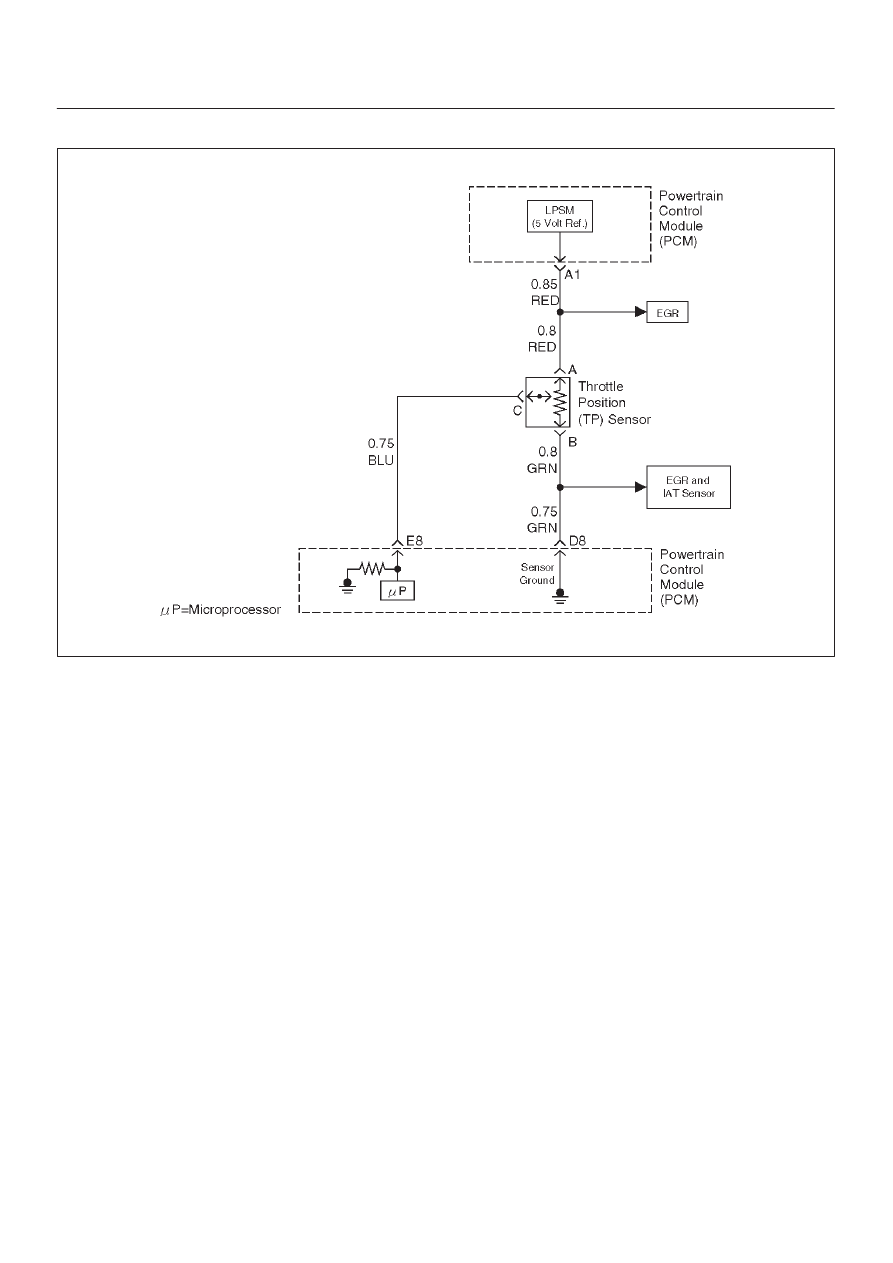
Circuit Description
The throttle position (TP) sensor circuit provides a voltage
signal that changes relative to throttle blade angle. The
signal voltage will vary from about 0.6 volts at closed
throttle to about 4.5 volts at wide open throttle (WOT).
The TP signal is used by the powertrain control module
(PCM) for fuel control and many of the PCM-controlled
outputs. The PCM monitors throttle position and
compares actual throttle position from the TP sensor to a
predicted TP value calculated from engine speed. If the
PCM detects an out-of-range condition, DTC P0121 will
set.
Conditions for Setting the DTC
D
The engine is running.
D
No MAP DTCs, or P0121, P0122, P0123 are set.
D
MAP reading is below 55 kPa.
D
Throttle is steady, throttle angle is changing less than
1%.
D
Predicted throttle angle is not close to actual throttle
angle.
D
Above conditions are present for a total of 12.5
seconds over a 25-second period of time.
Action Taken When the DTC Sets
D
The PCM will illuminate the malfunction indicator lamp
(MIL) after the second consecutive trip in which the
fault is detected.
D
The PCM will store conditions which were present
when the DTC was set as Freeze Frame and in the
Failure Records data.
D
The PCM will use a default throttle position based on
mass air flow and RPM.
Conditions for Clearing the MIL/DTC
D
DTC P0121 can be cleared by using the Tech 2 “Clear
info ” function or by disconnecting the PCM battery
feed.
Diagnostic Aids
Check for the following conditions:
D
Skewed MAP signal or faulty Map sensor – An
incorrect MAP signal may cause the PCM to incorrectly
calculate the predicted TP sensor value during high
engine load situations. Check for an unusually low
MAP reading. This condition can cause DTC P0121 to
be set.
D
Poor connection at PCM – Inspect harness connectors
for backed-out terminals, improper mating, broken
locks improperly formed or damaged terminals, and
poor terminal-to-wire connection.
D
Damaged harness – Inspect the wiring harness for
damage. If the harness appears to be OK, observe the
ECT display on the Tech 2 while moving connectors
and wiring harnesses related to the sensor. A change
in the display will indicate the location of the fault.
If DTC P0121 cannot be duplicated, the information
included in the Failure Records data can be useful in
determining vehicle mileage since the DTC was last set.