Opel Frontera UBS. Manual - part 2924


  Index      Opel     Opel Frontera UBS - service repair manual 1998-2002 year


Search            


Content   ..  2922  2923  2924  2925   ..


Opel Frontera UBS. Manual - part 2924


SUPPLEMENTAL RESTRAINT SYSTEM

9J–49

10. Install glove box cover.

11. Install glove box assembly with lid.

12. Install ECM and SDM cover.
13. Install rear console assembly and connect harness

connector.

14. Install front console assembly.
15. Install gear control knob.
16. Enable the SRS (Refer to “Enabling the SRS” in this

section).

Pretensioner Seat Belt (If so equipped)

Service Precaution

WARNING: WHEN PERFORMING SERVICE ON OR
AROUND THE PRETENSIONER SEAT BELT OR THE
PRETENSIONER SEAT BELT WIRING, FOLLOW THE
PROCEDURES LISTED BELOW TO TEMPORARILY
DISABLE THE PRETENSIONER SEAT BELT.
FAILURE TO FOLLOW PROCEDURES COULD
RESULT IN POSSIBLE THE PRETENSIONER SEAT
BELT DEPLOYMENT, PERSONAL INJURY OR
OTHERWISE UNNEEDED THE PRETENSIONER
SEAT BELT REPAIR.

AS A PRECAUTION, WEAR GLOVES AND SAFETY
GLASSES WHEN PERFORMING THE
PRETENSIONER SEAT BELT. WHEN DEPLOY A LIVE
PRETENSIONER SEAT BELT AT OUTSIDE THE
VEHICLE, DEPLOYMENT HARNESS SHALL REMAIN
SHORTED AND NOT BE CONNECTED TO A POWER
SOURCE UNTIL THE PRETENSIONER SEAT BELT IS
TO BE DEPLOYED. THE PRETENSIONER SEAT
BELT WILL IMMEDIATELY DEPLOY WHEN A POWER
SOURCE IS CONNECTED TO IT. CONNECTING THE
DEPLOYMENT HARNESS SHOULED ALWAYS BE
THE FINAL STEP IN THE PRETENSIONER SEAT
BELT DEPLOYMENT PROCEDURE. FAILURE TO
FOLLOW PROCEDURES IN THE ORDER LISTED
COULD RESULT IN PERSONAL INJURY.
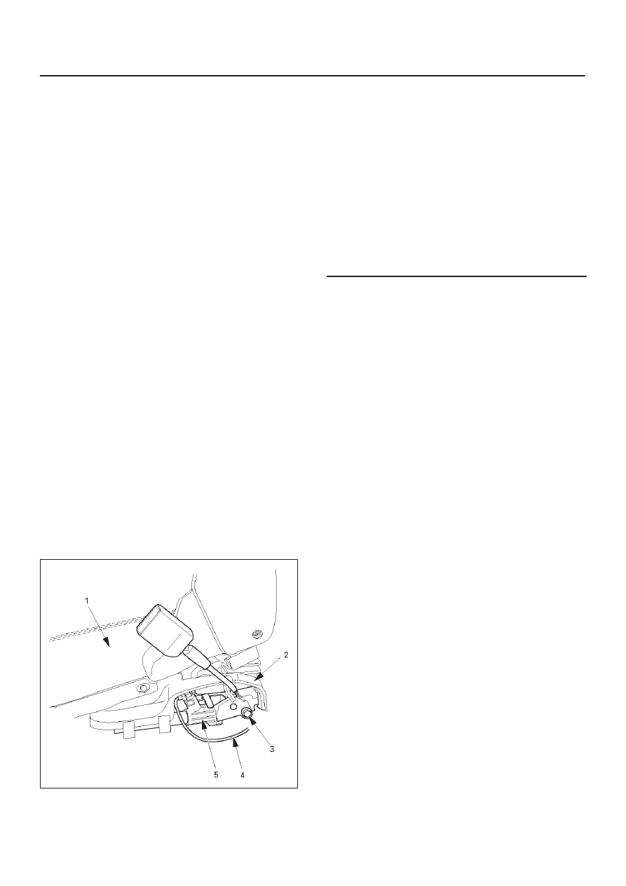
Parts Location

760RW028

Legend

(1) Seat
(2) Pretensioner Cover
(3) Bolt
(4) Pretensioner Harness
(5) Pretensioner

Removal

1. Turn ignition switch to “LOCK”, remove key.
2. Remove the foot rest located behind the seat.
3. Remove the cover on seat slide.
4. Disconnect the 2-pin connector at the base of the

seat.

5. Remove four fixing bolts the seat slide and remove

seat.

6. Remove the pretensioner seat belt cover.
7. Remove the pretensioner seat belt assembly.

Installation

1. Install the pretensioner seat belt assembly.
2. Install the pretensioner seat belt cover.
3. Install the seat on seat slide and four fixing bolts.
4. Connect the yellow 2-pin connector at the base of the

seat.

5. Install the cover on seat slide.
6. Install the foot rest located behind the seat.

SUPPLEMENTAL RESTRAINT SYSTEM

9J–50

Main Data and Specifications

Fastener Tightening Specification

Application

N·m

Kg·m

Lb Ft

Lb In.

SDM

10

1.0

87

Driver air bag fixing bolt

8.8

0.9

78

Steering wheel fixing bolt

34

3.5

25

Steering column (dash panel side fixing bolts)

19

1.9

14

Steering column (Pedal bracket fixing bolt)

17

1.7

13

Steering column (Universal joint fixing bolt)

25

2.6

18

Passenger Air Bag fixing bolts and nuts

6

0.6

52

9J1–1

RESTRAINT CONTROL SYSTEM

RESTRAINT CONTROL SYSTEM

CONTENTS

Service Precaution

9J1–1

. . . . . . . . . . . . . . . . . . . . . . 

Diagnostic Information

9J1–2

. . . . . . . . . . . . . . . . . . . 

System Schematic

9J1–4

. . . . . . . . . . . . . . . . . . . . . . 

SRS Diagnostic System Check

9J1–4

. . . . . . . . . . . . 

Chart A  SDM Integrity Check

9J1–6

. . . . . . . . . . . . . 

Chart B  “AIR BAG” Warning Lamp
 Comes “ON” Steady

9J1–8

. . . . . . . . . . . . . . . . . . . . 

Chart C  “AIR BAG” Warning Lamp
 Does Not Come “ON” Steady

9J1–10

. . . . . . . . . . . . . 

DTC 15  Passenger Deployment Loop
 Resistance High

9J1–13

. . . . . . . . . . . . . . . . . . . . . . . . 

DTC 16  Passenger Deployment loop
 Resistance Low

9J1–15

. . . . . . . . . . . . . . . . . . . . . . . . 

DTC 17  Passenger Deployment Loop
 Open

9J1–17

. . . . . . . . . . . . . . . . . . . . . . . . . . . . . . . . . . 

DTC 18  Passenger Deployment Loop
 Short To Ground

9J1–19

. . . . . . . . . . . . . . . . . . . . . . . . 

DTC 19  Passenger Deployment Loop
 Short To B+

9J1–21

. . . . . . . . . . . . . . . . . . . . . . . . . . . . 

DTC 21  Driver Deployment Loop
 Resistance High

9J1–23

. . . . . . . . . . . . . . . . . . . . . . . . 

DTC 22  Driver Deployment Loop
 Resistance Low

9J1–26

. . . . . . . . . . . . . . . . . . . . . . . . 

DTC 24  Driver Deployment Loop
 Short To Ground

9J1–29

. . . . . . . . . . . . . . . . . . . . . . . . 

DTC 25  Driver Deployment Loop
 Short To B+

9J1–31

. . . . . . . . . . . . . . . . . . . . . . . . . . . . 

DTC 26  Driver Deployment Loop Open

9J1–33

. . . . 

DTC 51  Air Bag Deployment Event
 Commanded

9J1–35

. . . . . . . . . . . . . . . . . . . . . . . . . . . 

DTC 53  Deployment Commanded With
 Deployment Loop Fault Or Energy
 Reserves Out Of Range

9J1–37

. . . . . . . . . . . . . . . . . 

DTC 61  Warning Lamp Circuit Failure

9J1–39

. . . . . 

DTC 71  Internal SDM Fault

9J1–41

. . . . . . . . . . . . . . 

DTC 29  Passenger Pretensioner Loop
 Short To Ground

9J1–43

. . . . . . . . . . . . . . . . . . . . . . . . 

DTC 31  Passenger Pretensioner Loop
 Resistance High

9J1–45

. . . . . . . . . . . . . . . . . . . . . . . . 

DTC 32  Passenger Pretensioner loop
 Resistance Low

9J1–47

. . . . . . . . . . . . . . . . . . . . . . . . 

DTC 33  Passenger Pretensioner Loop
 Short To Voltage

9J1–49

. . . . . . . . . . . . . . . . . . . . . . . . 

DTC 34  Passenger Pretensioner Loop
 Open

9J1–51

. . . . . . . . . . . . . . . . . . . . . . . . . . . . . . . . . . 

DTC 41  Driver Pretensioner Loop
 Resistance High

9J1–53

. . . . . . . . . . . . . . . . . . . . . . . . 

DTC 42  Driver Pretensioner Loop
 Resistance Low

9J1–55

. . . . . . . . . . . . . . . . . . . . . . . . 

DTC 44  Driver Pretensioner Loop
 Open

9J1–57

. . . . . . . . . . . . . . . . . . . . . . . . . . . . . . . . . . 

DTC 45  Driver Pretensioner Loop
 Short To Ground

9J1–59

. . . . . . . . . . . . . . . . . . . . . . . . 

DTC 46  Driver Pretensioner Loop
 Short To Voltage

9J1–61

. . . . . . . . . . . . . . . . . . . . . . . . 

DTC 52  Pretensioner Deployment
 Event Commanded

9J1–63

. . . . . . . . . . . . . . . . . . . . . 

Service Precaution

WARNING: IF SO EQUIPPED WITH A
SUPPLEMENTAL RESTRAINT SYSTEM (SRS),
REFER TO THE SRS COMPONENT AND WIRING
LOCATION VIEW IN ORDER TO DETERMINE
WHETHER YOU ARE PERFORMING SERVICE ON OR
NEAR THE SRS COMPONENTS OR THE SRS
WIRING. WHEN YOU ARE PERFORMING SERVICE
ON OR NEAR THE SRS COMPONENTS OR THE SRS
WIRING, REFER TO THE SRS SERVICE
INFORMATION. FAILURE TO FOLLOW WARNINGS
COULD RESULT IN POSSIBLE AIR BAG
DEPLOYMENT, PERSONAL INJURY, OR
OTHERWISE UNNEEDED SRS SYSTEM REPAIRS.

CAUTION: Always use the correct fastener in the
proper location. When you replace a fastener, use
ONLY the exact part number for that application.
ISUZU will call out those fasteners that require a
replacement after removal. ISUZU will also call out
the fasteners that require thread lockers or thread
sealant. UNLESS OTHERWISE SPECIFIED, do not
use supplemental coatings (Paints, greases, or other
corrosion inhibitors) on threaded fasteners or
fastener joint interfaces. Generally, such coatings
adversely affect the fastener torque and the joint
clamping force, and may damage the fastener. When
you install fasteners, use the correct tightening
sequence and specifications. Following these
instructions can help you avoid damage to parts and
systems.

SECTION

RESTRAINT CONTROL SYSTEM

9J1–2

Diagnostic Information

CAUTION: When  fasteners are removed, always
reinstall them at the same location from which they
were removed. if a fastener needs to be replaced, use
the correct part number fastener for that application.
if the correct part number fastener is not available, a
fastener of equal size and strength (or stronger) may
be used. fasteners that are not reused, and those
requiring thread locking compound will be called
out. the correct torque value must be used when
installing fasteners that require it. if the above
conditions are not followed, parts or system damage
could result.

Diagnostic Procedures

WARNING: TO AVOID DEPLOYMENT WHEN
TROUBLESHOOTING THE SRS, DO NOT USE
ELECTRICAL TEST EQUIPMENT SUCH AS A
BATTERY–POWERED OR AC–POWERED
VOLTMETER, OHMMETER, ETC., OR ANY TYPE OF
ELECTRICAL EQUIPMENT OTHER THAN THAT
SPECIFIED IN THIS MANUAL.  DO NOT USE A NON
POWERED, PROBE–TYPE TESTER.
INSTRUCTIONS IN THIS MANUAL MUST BE
FOLLOWED CAREFULLY, OTHERWISE PERSONAL
INJURY MAY RESULT.

The diagnostic procedures used in this section are
designed to aid in finding and repairing SRS problems.
Outlined below are the steps to find and repair SRS
problems quickly and effectively.  Failure to carefully
follow these procedures may result in extended
diagnostic time, incorrect diagnosis and incorrect parts
replacement.

1. Perform The “SRS Diagnostic System Check”.

The “SRS Diagnostic System Check” should always
be the starting point of any SRS diagnostics.  The
“SRS Diagnostic System Check” checks for proper
“AIR BAG” warning lamp operation and checks for
SRS trouble codes using both “Flash Code” and
“Scan Tool” Methods.

2. Refer To The Proper Diagnostic Chart As Directed

By The “SRS Diagnostic System Check”.
The “SRS Diagnostic System Check” will lead you to
the correct chart to diagnose any SRS problems.
Bypassing these procedures may result in extended
diagnostic time, incorrect diagnosis and incorrect
parts replacement.

3. Repeat The “SRS Diagnostic System Check”

After Any Repair Or Diagnostic Procedures Have
Been Performed.
Preforming the “SRS Diagnostic System Check” after
all repair or diagnostic procedures will assure that the
repair has been made correctly and that no other
conditions exist.

Diagnostic Codes

The Sensing and Diagnostic Module (SDM) maintains a
history record of all diagnostic codes that have been

detected since the SRS codes were last cleared during
service.

1. Active Codes — Faults that are presently detected

this ignition cycle.  Active codes are stored in RAM
(Random Access Memory).

2. History Codes — All faults detected since the last

time the history fault memory was cleared.  History
codes are stored in EEPROM. (Electronically
Erasable Programmable Read only Memory) 

How To Read Trouble Codes 

All codes (Active and history) can be read (or cleared) by
using a scan tool or equivalent.
If a PDT is not available, have the vehicle serviced by
ISUZU dealer.

How To Clear Trouble Codes

Trouble codes can only be cleared by using a Scan Tool.
If a “scan tool” is not available then inform the owner of the
stored codes and suggest that the codes are cleared
upon the next visit to an Isuzu dealership.

Scan Tool Diagnostics

A scan tool can be used to read current and history codes
and to clear all history codes after a repair is complete.
The scan tool must be updated to communicate with the
SRS through a memory card or a manufacturer’s update
before it can be used for SRS diagnostics.  To use the
scan tool, connect it to the DLC connector and turn the
ignition switch “ON”.  Then follow the manufacturer’s
directions for communication with the SRS.  The scan tool
reads serial data from the SDM “Serial Data” output
(terminal 24) to the DLC connector (terminal 9).

Basic Knowledge Required

Before using this section of the Service Manual, there is
some basic knowledge which will be required.  Without
this knowledge, you will have trouble using the diagnostic
procedures in this section.  Use care to prevent harm or
unwanted deployment.  Read all cautions in the service
manual and on warning labels attached to SRS
components.

Basic Electrical Circuits

You should understand the basic theory of electricity
including series and parallel circuits, and understand the
voltage drops across series resistors.  You should know
the meaning of voltage (volts), current (amps), and
resistance (ohms).  You should understand what happens
in a circuit with an open or a shorted wire.  You should be
able to read and understand a wiring diagram.

“Flash Code” Diagnostics

Flash code diagnostics can be used to read active codes
and to determine if history codes are present but cannot
be used to clear codes or read history codes. Flash code
diagnostics is enabled by grounding by terminal 4
shorting to terminal 13 of the DLC connector with the
ignition switch “ON”. Grounding terminal 4 of the DLC
connector pulls the “Diagnostics Request” input (Terminal
1) of the SDM low and signals the SDM to enter the flash
code diagnostic display mode.


Content   ..  2922  2923  2924  2925   ..