Content .. 2917 2918 2919 2920 ..
Opel Frontera UBS. Manual - part 2919
SUPPLEMENTAL RESTRAINT SYSTEM
9J–29
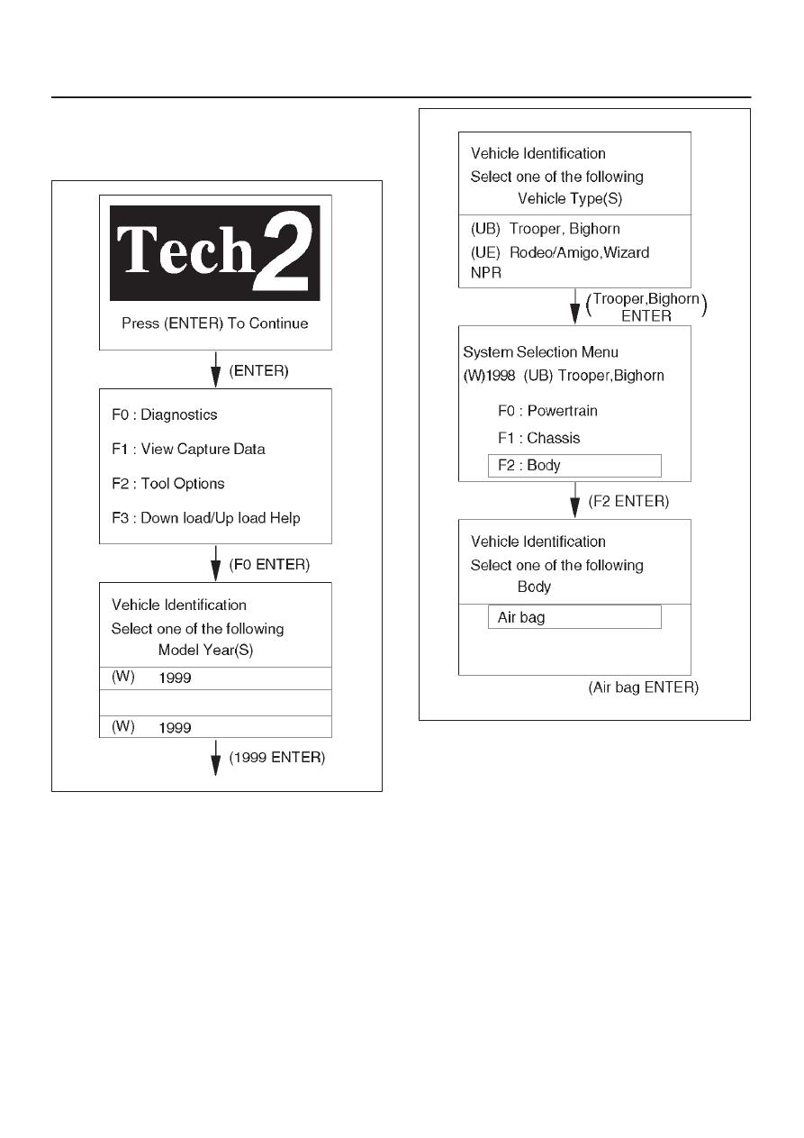
Operating Procedure
The power up screen is displayed when you power up the
tester with the Isuzu systems PCMCIA card. Follow the
operating procedure below.
060RX038
060RW019