Opel Frontera UBS. Manual - part 273
6D3–24 STARTING AND CHARGING SYSTEM
Stator Coil
1. Measure resistance between respective phases.
2. Measure insulation resistance between stator coil
and core with a mega–ohmmeter.
If less than standard, replace the coil.
066RS018
Brush
Measure the brush length.
If more than limit, replace the brush.
Standard: 10.mm (0.4134 in)
Limit: 8.4.mm (0.3307 in)
066RS019
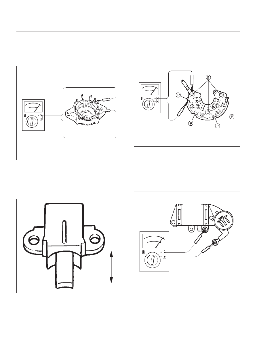
Rectifier Assembly
Check for continuity across “P” and “E” in the
×
100W
range of multimeter.
066RW002
Change polarity, and make sure that there is continuity in
one direction, and not in the reverse direction. In case of
continuity in both directions, replace the rectifier
assembly.
IC Regulator Assembly
Check for continuity across “B” and “F” in the
×
100W
range of multimeter.
066RS021
Change polarity, and make sure that there is continuity in
one direction, and not in the reverse direction. In case of
continuity in both directions, replace the IC regulator
assembly.
Reassembly
To reassemble, follow the disassembly steps in the
reverse order, noting the following points: